
Voltage Ampere and Temperature meter with PIC16F877A

The project described involves a sophisticated power supply measurement system utilizing a PIC Microchip. The primary function of the circuit is to measure voltage, current, and temperature, displaying the results on either an LED or LCD screen. The design is tailored for DIY electronics enthusiasts, facilitating ease of construction through a printed circuit board (PCB) that utilizes large tracks. This feature enhances the manufacturability of the board, especially using techniques like the "press-n-peel" method.
The heart of the circuit is the PIC16F877A or PIC16F887 microcontroller, which is programmed to perform analog-to-digital conversions (ADC). The ADC resolution is 10 bits, allowing for a maximum of 1024 discrete values. This setup is crucial for accurately measuring the input voltage and current. The voltage range is adjustable from 0 to 33V, but the PIC can only process voltages from 0 to 5V. Thus, a scaling mechanism is necessary to ensure that the input voltage is appropriately reduced within this range. The voltage resolution is calculated to be approximately 32.2mV per increment at the maximum voltage, while the current measurement spans from 0 to 3A, providing a resolution of about 2.9mA.
The display options include a standard LCD compatible with HD44780 driver chips, designed for a 2x16 character output, or a 6x7 segment LED display configured in a common anode arrangement. This flexibility allows the user to choose a display type that best fits their project needs. Additionally, the circuit can be configured via an RS232 terminal, enabling the user to set voltage and current conversion factors, enhancing its adaptability.
Programming the PIC is essential for the circuit's operation. The project suggests using a Microchip MPLAB ICD 2 programmer, although adaptations may be required for compatibility with other programming devices. The design also includes an IPSC connector for in-circuit programming, simplifying the process of updating the microcontroller firmware.
Power supply requirements for the circuit include a separate -12V, 0V, and +12V source, ensuring that the microcontroller and associated components operate within their specified voltage ranges. Overall, this project offers a comprehensive solution for measuring electrical parameters, combining ease of construction with functional versatility.This project was designed and constructed as enhancement to the 0-30V Stabilized Power Supply Project with the DIY electronics hobbyist in mind. The circuit uses a single PIC Microchip to perform the Voltage, Current and Temperature conversions and display functions.
The PCB Board uses large tracks and can easily be made using the "press-n-peel" method and a hobby drill. Components should be readily available anywhere in the world. Furthermore the hex files are available for the PIC16F877A and the PIC16F887 and the display can either be LCD or LED.
There is only one warning - do not attempt to construct this project unless you are sure what you are doing. Nobody else but you can make the decision to construct it and therefore you are solely responsible for what you are doing or not doing with it.
The PIC Microchip Processor must be programmed before it will function as a Volt & Amp meter. There are many internet sites and PIC programmers that you can use. I used a Microchip MPLAB ICD 2 during the project. You might need to made changes to the circuit to accommodate a different type of programmer, do read the programmers instructions carefully. The circuit relies on the internal analogue to digital converter (ADC) of the PIC Microchip Processor.
The accuracy is dependant on scaling the input voltage for the ADC for all three measurements. The good news is that both the PIC's which can be used for this project have 10-Bit resolution ADC units which should work adequately in most circumstances. In order to determine the resolution, simple to advanced mathematics can be used - I will use simple mathematics and present a basic explanation in order for you to get going on the project.
The Voltage of the PSU can be adjusted from 0 to 33V depending on the components in your circuit. The PIC can only measure voltages between 0 - 5V and represent the values measured as a 10bit binary number from 0 - 1024. In order to determine the voltage increments which can be measured one has to divide the scaled input voltage by 1024 and that equals: 33V/1024 = 32.2mV.
Similarly the current range is 0 to 3A. Which means that we can measure in 3.0/1024 = 2.9mA increments in a near perfect circuit. Best Voltage resolution at 33.0V - 32.2mV Best Current resolution at 3.0A - 2.9mA Features: ? Either a LED or LCD display can be used ? LCD Output is compatible with most LCD Displays with a HD44780 drive chip, it was designed for a 2 line x 16 character display ?
6 x 7 Segment LED Display using Common Anode displays ? Configuration via RS232 terminal to set Voltage and Current conversion factors ? Two PIC16F processors are supported, the 16F877A and 16F887 - separate hex files provided for download here ? IPSC Connector for Programming the PIC in circuit ? Separate -12V - 0 - +12V, Power Supply 🔗 External reference
Related Circuits
This circuit is used to convert a mono audio signal into a stereo signal that can be panned between the left and right channel by a 0-10V control signal, it is intended for analog synthesizer systems. The circuit is...
This circuit controls very accurately a fan of any size. Just adjust the associated resistors for a different type like the R6 resistor of 100 ohm, 2 watt type and you're all set. The above circuit diagram is for...
A new generation of intelligent, scriptable sensors/controllers is on the horizon. Traditionally, many simple machines utilized separate thermometer and control units. In contrast, this design presents a unified thermometric controller that can be programmed with simple scripts. It incorporates...
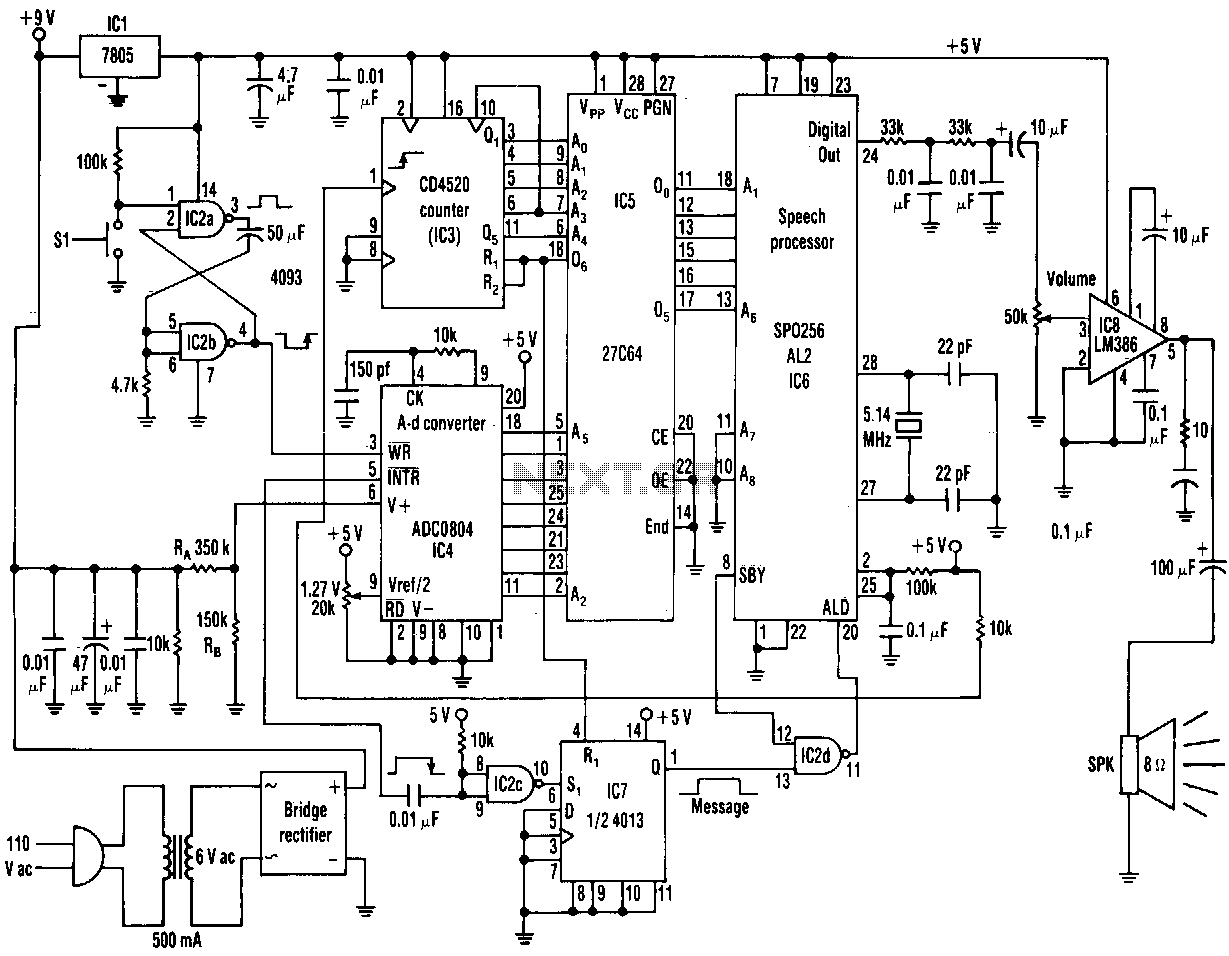
The range of this AC voltage monitor is 100 to 140 Vac, with a resolution of 1 V. The speech processor interprets an 8-bit binary input code from an analog-to-digital converter. The processor's pulse-code-modulated output then passes through a...
The Inter-Power SWR-5 upper right isn't worth a penny. Got it from a mate to use with a beacon, but I burnt it out with only 3.5-4W morse signal on 70cm. Removed the bridge and installed my own pick-up...
This circuit is a Digital Radar Speedometer that measures the speed of moving objects, particularly vehicles such as cars. The speed is displayed in kilometers per hour (KPH) and features a three-digit display. The radar operates using laser reflection...