
Programmable logic devices (CPLD)
CPLDs are integrated circuits that provide a versatile solution for digital logic design. They consist of an array of programmable logic blocks and interconnects, allowing designers to create complex digital systems without the need for discrete components. The architecture of a CPLD typically includes multiple macrocells, each capable of implementing combinational and sequential logic functions. These macrocells can be configured to perform a variety of tasks, such as multiplexing, demultiplexing, or arithmetic operations.
The design process for a CPLD begins with the use of hardware description languages (HDLs) such as VHDL or Verilog, which allow for the specification of the desired circuit behavior. Once the design is complete, it is synthesized using specialized software tools that translate the HDL code into a configuration file. This file is then uploaded to the CPLD via a programming interface, enabling the device to execute the designed logic functions.
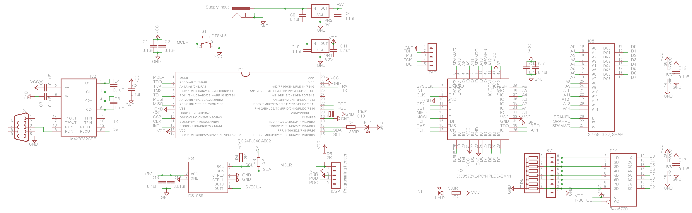
CPLDs are particularly beneficial in applications requiring rapid prototyping or iterative design, as they can be reprogrammed multiple times. This flexibility makes them ideal for use in digital signal processing, communication systems, and control applications. Additionally, CPLDs offer advantages such as reduced board space, lower power consumption, and improved reliability compared to traditional discrete logic solutions. Their ability to implement complex logic functions in a single package streamlines the design process and enhances overall system performance.Complex programmable logic devices (CPLDs) contain the building blocks for hundreds of 7400-serries logic ICs. Complete circuits can be designed on a PC and then uploaded to a CPLD for instant implementation.. 🔗 External reference
Related Circuits
This circuit is a stable frequency counter with an accuracy of 5 significant digits. It operates within a frequency range of 0 to 30 MHz and has an input sensitivity greater than 100 mV. The probe connects to the...
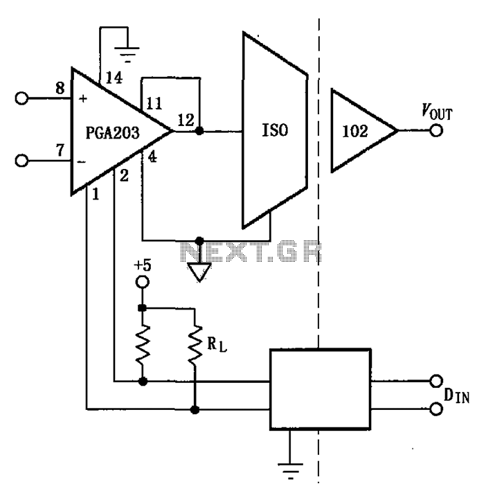
The PGA203 and isolation amplifier IS0102 form an isolated programmable gain instrumentation amplifier circuit. The PGA203 amplifies the input signal, and the output from the isolation amplifier IS0102 is VOUT. Additionally, a DIN digital optocoupler is used for the...
Features: 1. The operating voltage is low, functioning with a single supply of 2.0V. 2. Power consumption is minimal, with a supply current of 5 µA at 32 kHz and 130 µA at 1 MHz. 3. It has a...
This is an FM transmitter circuit that utilizes logic gates. The circuit features a radio frequency (RF) oscillator, which operates with a 10.7 MHz ceramic filter. The FM transmitter circuit is designed to modulate audio signals onto a carrier frequency...
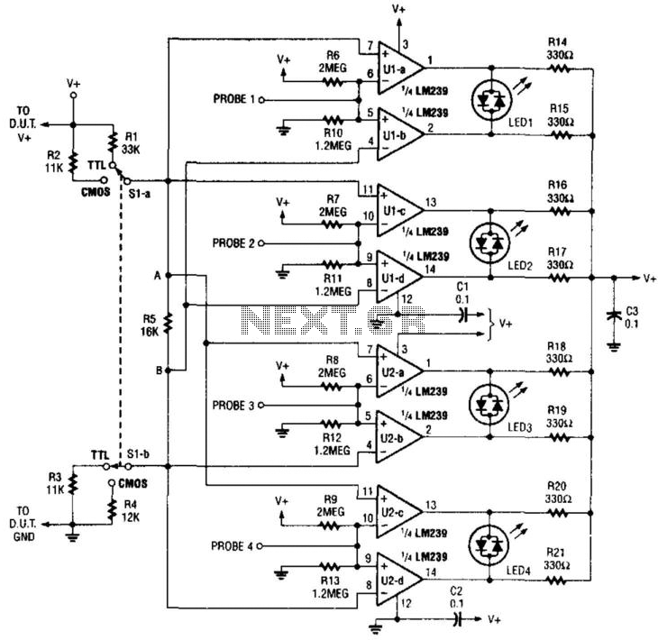
This logic probe features four channels and employs two quad comparator integrated circuits to drive four bicolor LEDs. The SI and SIB pins are used to set the comparator trip levels for TTL and CMOS logic families. Resistors R6...
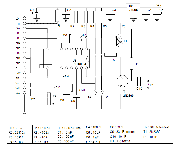
The basic idea comes from the AN592 Microchip application note: "Frequency counter using PIC16C5x". where you may find a simple software which implements a frequency counter using a PIC microcontroller. I wrote a specifically designed software to improve the...