
Proximity alarm

To set up the circuit, adjust C1 and C2 to approximately one-half of their maximum value and apply power. The circuit should oscillate without producing sound. Using a non-metallic screwdriver, carefully adjust C1 and C2, one at a time, to a lower value until the circuit ceases oscillation, at which point buzzer BZ1 will sound off. Slightly increase the value of either C1 or C2 until the oscillator restarts; this configuration represents the most sensitive setting of the circuit.
The circuit operates on the principle of an RC oscillator, where the resistances and capacitances dictate the oscillation frequency. Inverters Ula and Ulb function as the primary oscillating components, while the capacitors C1 and C2 form a timing network that influences the charge and discharge cycles, thereby determining the oscillation frequency. The output from the voltage-coupler circuit, which includes capacitors C3 and diodes D1 and D2, ensures that the positive DC voltage is adequately filtered and stabilized before being fed into the third inverter U1c.
The third inverter serves as a buffer and an additional control stage, ensuring that the output remains low until the circuit is activated by the detected presence of a hand. The configuration of Q1, likely a transistor, acts as a switch that controls the buzzer BZ1. When the circuit detects the proximity of a hand, it triggers the oscillator to stop, allowing current to flow through Q1 and activating the buzzer, thus providing an audible alert.
This circuit is highly sensitive to nearby objects, making it suitable for applications such as intrusion detection or proximity sensing. Proper calibration of C1 and C2 is essential for optimal performance, allowing the circuit to react to minimal disturbances within its detection range. The use of non-metallic tools for adjustments is critical to avoid unintended interference with the circuit's operation.Inverters Ula and Ulb are connected in a simple RC oscillator circuit. The frequency is determined by the values of Rl, Cl, C2; and the internal characteristics of the integrated circuit. As long as the circuit is oscillating, a positive dc voltage is developed at the output of the voltage-coupler circuit: C3, Dl, D2 and C4.
The dc voltage is applied to the input of Ulc—the third inverter amplifier—keeping its output in a low state, which keeps Ql turned off so that no sound is produced by BZ1. With Cl and C2 adjusted to the most sensitive point, the pickup plate will detect a hand 3 to_5-inches away and sound an alert.
Set Cl and C2 to approximately one-half of their maximum value and apply power to the circuit. The circuit should oscillate and no sound should be heard. Using a non-metallic screwdriver, carefully adjust Cl and C2, one at a time, to a lower value until the circuit just ceases oscillation: Buzzer BZ1 should sound off. Back off either Cl or C2 just a smidgen until the oscillator starts up again—that is the most sensitive setting of the circuit.
Related Circuits
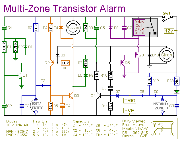
This transistor-based alarm features automatic exit and entry delays, along with a timed bell cut-off and system reset. In addition to the exit/entry zone, the basic alarm board includes one instant zone, which is sufficient for many applications. However,...

This temperature monitor alarm circuit continuously monitors room temperature and emits a beep when the temperature falls below 20 degrees Celsius. The ability to constantly check the temperature can help reduce air conditioning costs by reminding users to turn...
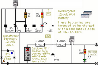
The following circuit illustrates an Alarm Power Supply Circuit Diagram. Features include a 1-amp current output, suitable for a Modular Burglar Alarm operating at 12 volts. The Alarm Power Supply Circuit is designed to provide a stable and reliable power...
The emergency driver unit includes a battery charger and electronic circuitry housed in a compact case. It features battery protection for emergency lighting against overcurrent and heat. Additionally, it has protection for the liquid crystal display (LCD) screen against...
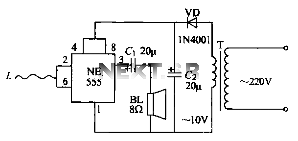
The manpower inductive alarm circuit is simple and practical. When a person's hand approaches the sensing line, the alarm emits a sound, making it suitable for male electrical burglar alarms. The induction line L is approximately 50 cm long....

This light alarm schematic circuit is designed using common electronic components, as illustrated in the circuit diagram below. The light alarm circuit will activate an alarm as soon as the drawer is opened and light falls on the Darlington...