
program pic16f887 using linux
The tutorial provides a structured approach to programming PIC microcontrollers under a Linux environment, emphasizing the importance of the Small Device C Compiler (sdcc) for generating the necessary hex files. The tutorial's focus on specific PIC models and the use of tested programmers ensures a reliable programming experience. The inclusion of configuration words is crucial, as they define the operational parameters of the microcontroller. Understanding how to manipulate these settings through the provided code examples enhances the user's ability to customize their applications effectively. The use of an infinite loop for LED control exemplifies basic programming principles while allowing users to visualize the outcomes of their programming efforts. Overall, this guide serves as a valuable resource for Linux users seeking to engage with PIC microcontrollers, bridging the gap between code development and hardware programming.One of the drawbacks for some of us is that Linux support for PICs is not very well known. The information is out there, but no one has laid out the process of going from writing C code to programming a chip. Written for Linux users that are familiar with microcontrollers, basic circuits, the C programming language, and can read a datasheet,
this how-to should get you up and programming a PIC quickly with Linux. The Small Device C Compiler, sdcc is what will be used to create the. hex file needed to program a PIC. Support for PICs is still growing, and still in beta, so be aware that things outside the code and chips of this article may need some debugging. However, like every other open source project out there, more contributing users will help the project.
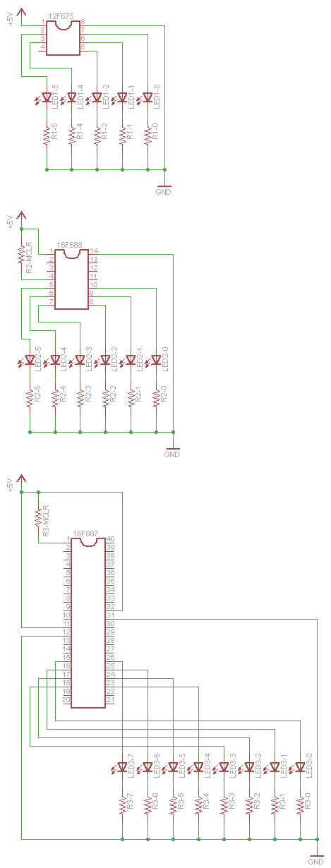
Best of all, it is free, with ports to Windows and MacOS X, this is a compiler that handles many architectures and devices without the program limit of free versions of for-pay compilers that are limited to Windows. Sdcc is available through various distributions` package managers including Ubuntu and Fedora. Three different PIC chips were used in the writing of this tutorial: the 40 pin PIC16F887, the 14 pin PIC16F688, and the 8 pin PIC12F675.
You can follow along with any of these chips as well as other chips. We will be using two programmers, Olimex`s PICStart+ compatible PIC-MCP-USB programmer, and Microchip`s PICkit 2. Both programmers have been tested to work with the three chips used here. Note that Microchip touts the PICkit 3 as a replacement for the PICkit 2. It is not a replacement for the PICkit 2 as there are no Linux drivers for the PICkit 3, so do not buy the PICkit 3 thinking it will work in Linux.
There is also another program that claims to work with a range of DIY PIC programmers: PICPgm. We have not tried this program or any of the DIY programmers at this point. We know there are other PIC programmers out there, both cheap and expensive, that have not been mentioned. Perhaps a PIC programmer roundup is in need of writing. The code for this how-to is a kind of hello world program using LEDs. The code for this is hosted on Github, you can follow along with the blink. c file for the PIC16F887, PIC16F688, or PIC12F675. Also included are working. hex files. Here is the PIC16F887 code as a reference as we walk through each major operation: The first line is the #include for the header file of the particular chip you will be using.
It tells the compiler which registers are available and where they are located in memory. In most systems, the header files will be in /usr/share/sdcc/include. Then we setup the configuration word or words fuses. They are only able to be written when the chip is programmed, but we can define them here so we don`t have to manually program them later. The PIC16F887 has the address for the configuration words defined in its header file as _CONFIG1 and _CONFIG2.
The PIC16F688 and PIC12F675 do not have the configuration word address defined in their header (we said sdcc was in beta, didn`t we ), so we just use the address of the configuration word: 0G—2007. The configuration words are specific to the chip model and application and are described in the chapter Special Features of the CPU in each of the respective chips` datasheets.
In the blink. c samples, the configuration word is just a 16bit hexadecimal word, but the word can be made more human readable by ANDing together the configuration options. Check out the chips` header files for the names of the options. In the void main(), we set the PORTC tristate register, TRISC to all outputs. The PIC12F675 has only one port, GPIO, and its tristate register is TRISIO. After setting the tristate register, we enter an infinite loop with while(1). Inside that loop is a delay loop so that we can see the LEDs changing. Following the delay loop, the display co 🔗 External reference
Related Circuits
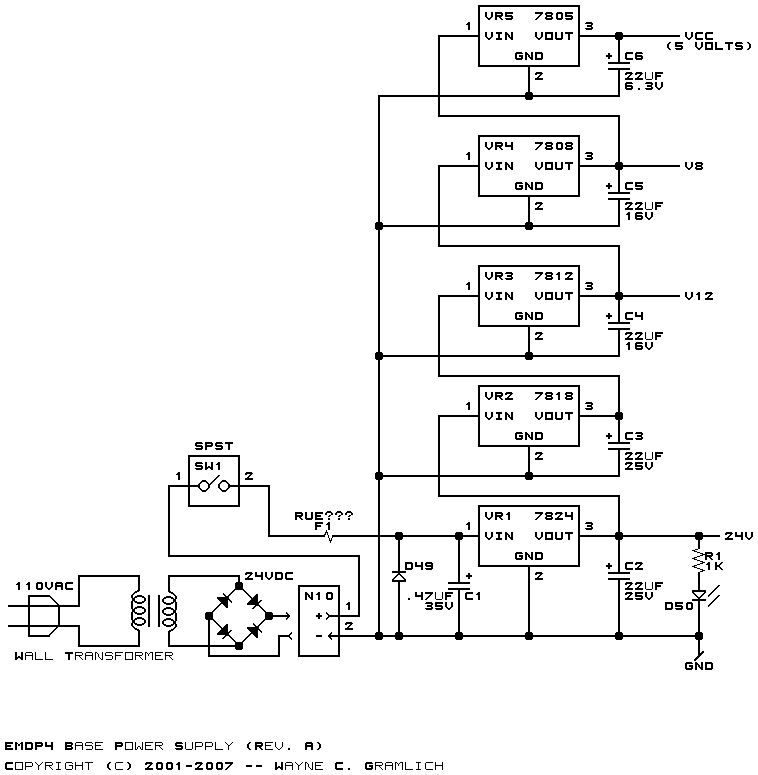
The 5-volt microcontroller interfaces with the RS-232 serial connector and the USB-B connector. It is responsible for communicating with the checker, controlling the status LEDs, and setting the voltage for the low-voltage microcontroller. The low-voltage microcontroller operates at the...
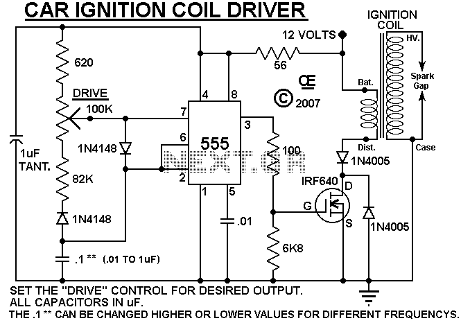
A simple design based on a 555 to drive a car ignition coil. This was designed for a small electric fence to protect a vegetable garden from small animals called marmots. Last year, they ate one of the crops...

This circuit is a touch switch circuit, similar to a touch door alarm. It utilizes a 555 timer as the core component of the touch switch circuit. The operation begins when the plate is touched, triggering the 555 timer....
The simplest method of detecting metal is through a beat frequency oscillator. The circuit consists of two balanced oscillators: one serves as the detector element while the other provides a reference signal. The reference oscillator frequency is set to...
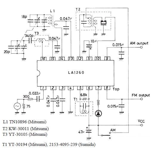
This FM IF MW radio receiver circuit schematic utilizes the LA1260 integrated circuit (IC), which is suitable for AM and FM radio receiver electronic projects. The LA1260 incorporates numerous functions and features essential for radio receiver applications, including a...
Humanity has long grappled with the concept of Time, often seeking ways to interact with it meaningfully. A proposed solution is a knocking platform designed to address these fundamental needs, exemplified by the Knock Block KUI and its associated...