
Infrared light trap circuit
The infrared light valve circuit is designed to provide an effective alarm system, utilizing a transmitter and receiver configuration that minimizes interference from ambient light. The transmitter employs a NE 555 timer (IC1), which is configured in astable mode to generate a series of pulses. These pulses are directed to an infrared LED (D1, LD274), which emits infrared light at a frequency determined by the variable resistor P1 (10 kOhm). The frequency of these pulses can be adjusted to optimize the performance of the system.
On the receiving end, a phototransistor (T1, BPW40) detects the infrared light emitted by the LED. The output pulses from the phototransistor are coupled through a capacitor (C4, 47 nF) to the positive input of an operational amplifier (IC2, LM 741). The operational amplifier is configured with a feedback network that includes resistors (R1, R2, R3, R4, R5, R6, R7, R8, R9, R10, R11) and capacitors (C1, C2, C3, C6, C5) to stabilize the gain and set the frequency response of the circuit. The RC network between the output and inverting input of the op-amp ensures that the circuit maintains a low frequency response, with a cutoff around 7.2 kHz, which is critical for minimizing false triggers from unwanted noise.
When the phototransistor receives the infrared pulses, it generates a corresponding output voltage that is amplified by the operational amplifier. The amplified signal is then used to drive a transistor (T2, BC547), which controls a relay (RE1). The relay acts as a switch, allowing for the activation of an alarm or other devices when the infrared beam is interrupted.
To ensure proper operation, it is essential to position the infrared LED and phototransistor so that they are aligned with each other, allowing for optimal light transmission and reception. The adjustment of P1 allows for fine-tuning of the sensitivity of the circuit, ensuring that the relay activates only when the infrared signal is disrupted. The overall design provides a robust solution for alarm systems, leveraging the simplicity and reliability of infrared technology.This infrared light valve has more parts, so it works better and more reliable for alarms. The circuit responds less ambient light. The light valve consists of a transmitter and a receiver. The transmitter consists of a NE 555 which provides pulses to the infrared LED (D1) are fed. The frequency of the pulses is set to P1. On the receiver side we see the photo transistor T1 receives the pulses from D1. The pulses through C4 to the positive input of op amp IC2 led. Between the output of IC2 and the minus input is an RC network that ensures the lowest at about 7.2 kHz amplitude issues. R1 = 1 kOhm R2 = 2.7 kOhm R3 = 470 ? R4 = 100 kOhm R5, R6 = 270 kOhm R7, R8 = 47 kOhm R9 = 270 ? R10 = 180 kOhm R11 = 10 kOhm P1 = 10 kOhm C1 = 15 nF C2 = 10 nF C3, C6 = 100 uF C4, C5 = 47 nF C7 = 2.2 uF C8 = 4.7 uF Then the gain of the 741 the least inhibited. When the pulses of the transmitter frequency which is the output voltage of 741 the highest. This allows guiding and T2 the relay is energized. The correct adjustment is simple. Place the phototransistor and the infrared LED so opposed that they can see each other. Control over P1 such that the relay picks up. D1 = LD274 D2, D3, D4 = 1N4148 T1 = BPW40 T2 = BC547 IC1 = NE 555 IC2 = LM 741 RE1 = 1 x relay switch
🔗 External reference
Related Circuits
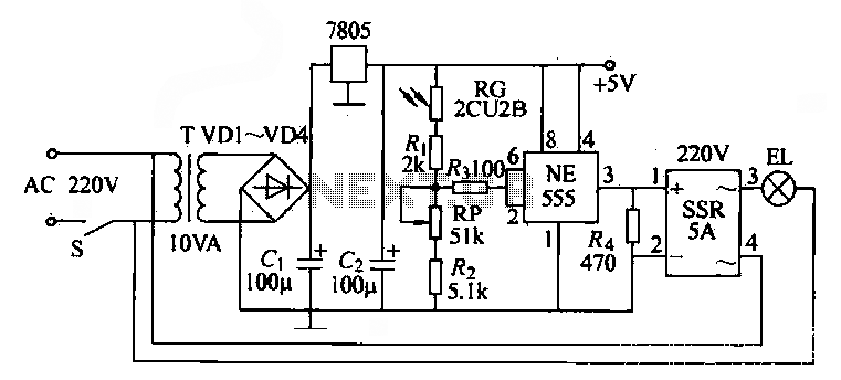
The NE555 time base circuit with an AC solid-state relay (SSR) can function as an automatic light switch circuit. The circuit diagram illustrates that during the day, the incandescent light is turned off due to the influence of the...
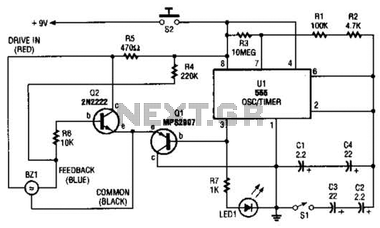
The electronic darkroom timer is constructed using a 555 oscillator/timer, a pair of general-purpose transistors, a buzzer, and an LED. The 555 timer (U1) is set up as an astable multivibrator, functioning as a free-running oscillator. The frequency of...
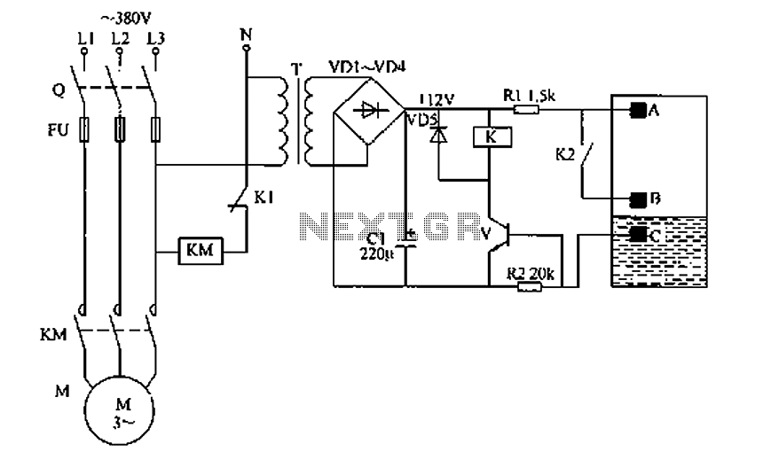
The liquid level automatic controller circuit consists of a power circuit, a level detection circuit, and a control implementation circuit. The power circuit is formed by a power transformer T, rectifier diodes YD1 to VD4, and a filter capacitor...
Many applications require low-frequency signal generators that can deliver high-performance, high-resolution signals. This design idea presents a circuit that generates frequencies from 0 to 1 MHz, providing sinusoidal, triangular, and square-wave outputs with frequency resolution better than 0. A...
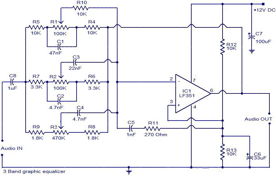
The circuit is a diagram of a simple three-band graphic equalizer circuit. An IC known as the LF351 is utilized in this design. The three-band graphic equalizer circuit is designed to adjust the amplitude of audio signals across three distinct...
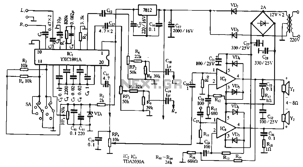
The ptPC1891A application circuit features a working state switch (SA) with a total of four options. It primarily utilizes ICs 11 and 12 to set different logical levels, as referenced in Table 5-12. The high level is denoted as...