
Pulse Induction Metal Detector

This project involves the design of a stable electronic unit that can be configured in three distinct ways using coils. The stability of the unit is a critical feature, ensuring consistent performance across various applications. The use of coils in different configurations allows for flexibility in operation, which can be tailored to specific requirements or preferences.
The inclusion of a piezo buzzer enhances the functionality of the unit, providing audible feedback or alerts when the circuit is activated. Piezo buzzers are known for their efficiency and reliability, making them suitable for integration into various electronic projects. The connection of the buzzer to the circuit should be done in such a way that it does not interfere with the primary operation of the unit. Typically, the buzzer can be connected to a digital output pin of a microcontroller or a transistor switch that is activated under certain conditions dictated by the circuit's logic.
When constructing the circuit, it is essential to ensure that all components are rated for the voltages and currents they will encounter. Proper grounding and power supply considerations must also be taken into account to avoid issues related to noise or instability. Additionally, the layout of the circuit should minimize interference and allow for easy access to the configuration options for the coils.
Safety precautions should be observed throughout the assembly process, as the project is to be built at the individual's risk. It is advisable to test each configuration of the coils separately to ascertain their performance before integrating them into a single unit. This systematic approach will help in identifying any potential errors or issues that may arise during operation.This project is offered totally Free for those who are interested in it. I have tried to make this article as complete as possible, but I will Not assume any lilability for any "Errors or Omissions" in this article. If Needed, I will attempt to help you as much as possible with any problems. However I have no control of your abilities or skills, so build it totally at your own risk! This unit is Extremely Stable, and features three possible configurations with the coils, as listed below. I can now supply a small Pizo Buzzer that works quite well on this unit. Well the reason why you can`t detect it is because the conducti 🔗 External reference
Related Circuits
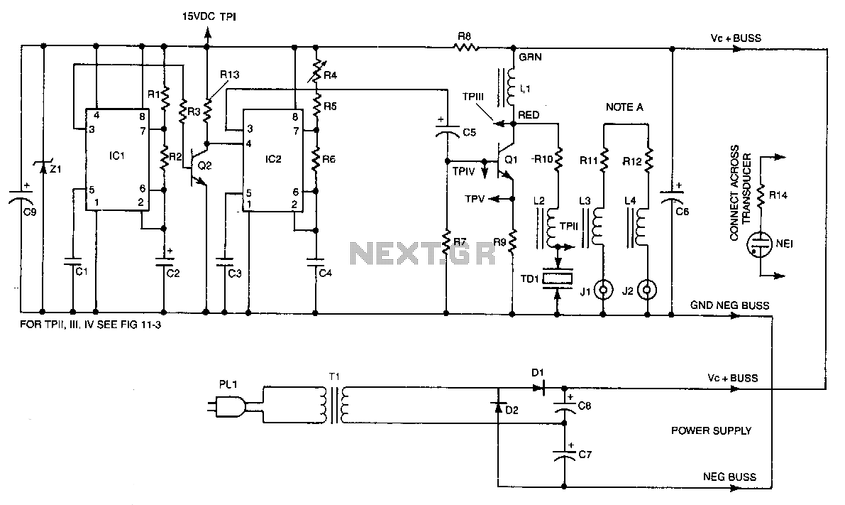
IC2 is a stable oscillator whose frequency and pulse width are determined by the values of R4, R5, R6, and C4. R4 is adjustable for precise frequency setting. The output from IC2 is at pin 3, which is capacitively...
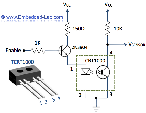
The heart rate measurement project utilizing fingertip photoplethysmography was constructed using salvaged components, specifically an infrared LED and a photodiode. Due to the nature of these parts, their specifications could not be provided in the article. The heart rate measurement...

A quad 2-input NAND Schmitt trigger circuit can be designed using the MC14093 CMOS type IC, which serves as a simple pulse width modulation (PWM) controller electronic project. This PWM controller is straightforward and requires only a few external...
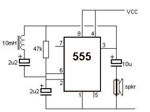
This metal detector electronic project schematic circuit is designed using a simple 555 timer integrated circuit. The schematic circuit requires a few external electronic components. The metal detector circuit utilizes the 555 timer IC in astable mode to generate a...

This text outlines preliminary plans for a frequency meter designed for a bat detector. The device measures the frequency of the local oscillator in a heterodyne type bat detector, serving as a valuable tool for bat identification. The frequency...

This circuit is a xenon lamp flash detector. It has a very low standby current requirement yet has very high sensitivity toward the light flashes from a xenon lamp. When connected to a flip-flop, it can serve as an...