
metal detector 555 timer
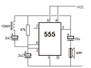
The metal detector circuit utilizes the 555 timer IC in astable mode to generate a frequency that is modulated by the presence of metal objects. The basic configuration includes the 555 timer, resistors, capacitors, and a speaker or buzzer to provide audio feedback when metal is detected.
In the schematic, the 555 timer is connected with two resistors and a capacitor to set the oscillation frequency. When metal is introduced into the detection area, it alters the inductance of a coil connected to the circuit, which in turn affects the timing characteristics of the 555 timer. This change in frequency is perceived as a change in tone or pitch from the output device, alerting the user to the presence of metal.
The circuit may also include a potentiometer to allow for sensitivity adjustments, enabling the user to fine-tune the detection range based on environmental conditions. Additionally, a simple LED indicator can be integrated to provide a visual cue alongside the audio signal, enhancing user experience.
Overall, this metal detector project represents an accessible and educational introduction to basic electronics and signal processing, demonstrating the practical application of the 555 timer IC in detecting metallic objects.This metal detector electronic project schematic circuit is designed using a simple 555 timer integrated circuit. As you can see in the schematic circuit, this metal detector electronic project requires few external electronic parts.
🔗 External reference
Related Circuits

An LED flasher circuit can be constructed using a 555 integrated circuit (IC). The use of the 555 IC allows for greater flexibility in adjusting the flashing rate of the LED. This LED flasher circuit is similar to other...

This circuit detects light and provides a voice warning. It responds to changes in light conditions, becoming active based on the position of switch S1. The circuit utilizes a light-dependent resistor (LDR) to sense ambient light levels. When the light...

This type of infrared proximity circuit is commonly utilized as an electric switch where physical contact is undesirable for hygiene reasons. For instance, infrared proximity sensors are frequently found in public drinking fountains and washrooms. The straightforward circuit described...

This water level sensor circuit utilizes a standard NAND logic gate to generate oscillation and detect water levels. The oscillation functionality is integrated within the circuit. The water level sensor circuit employs a NAND logic gate to create a square...
This timer is designed for individuals seeking to achieve a tan while minimizing excessive exposure to sunlight. A rotary switch allows the user to set the timer based on six classified photo-types. A photoresistor adjusts the preset time value...

Utilize the CA3164A BiMOS detector/alarm system for operation as a smoke detector with an electromechanical horn (refer to Fig. 40-la). The output driver at terminal 8 is employed, utilizing a large npn transistor Q3 with an active pull-up, while...