
Pulse width / voltage conversion circuit composed of TL082
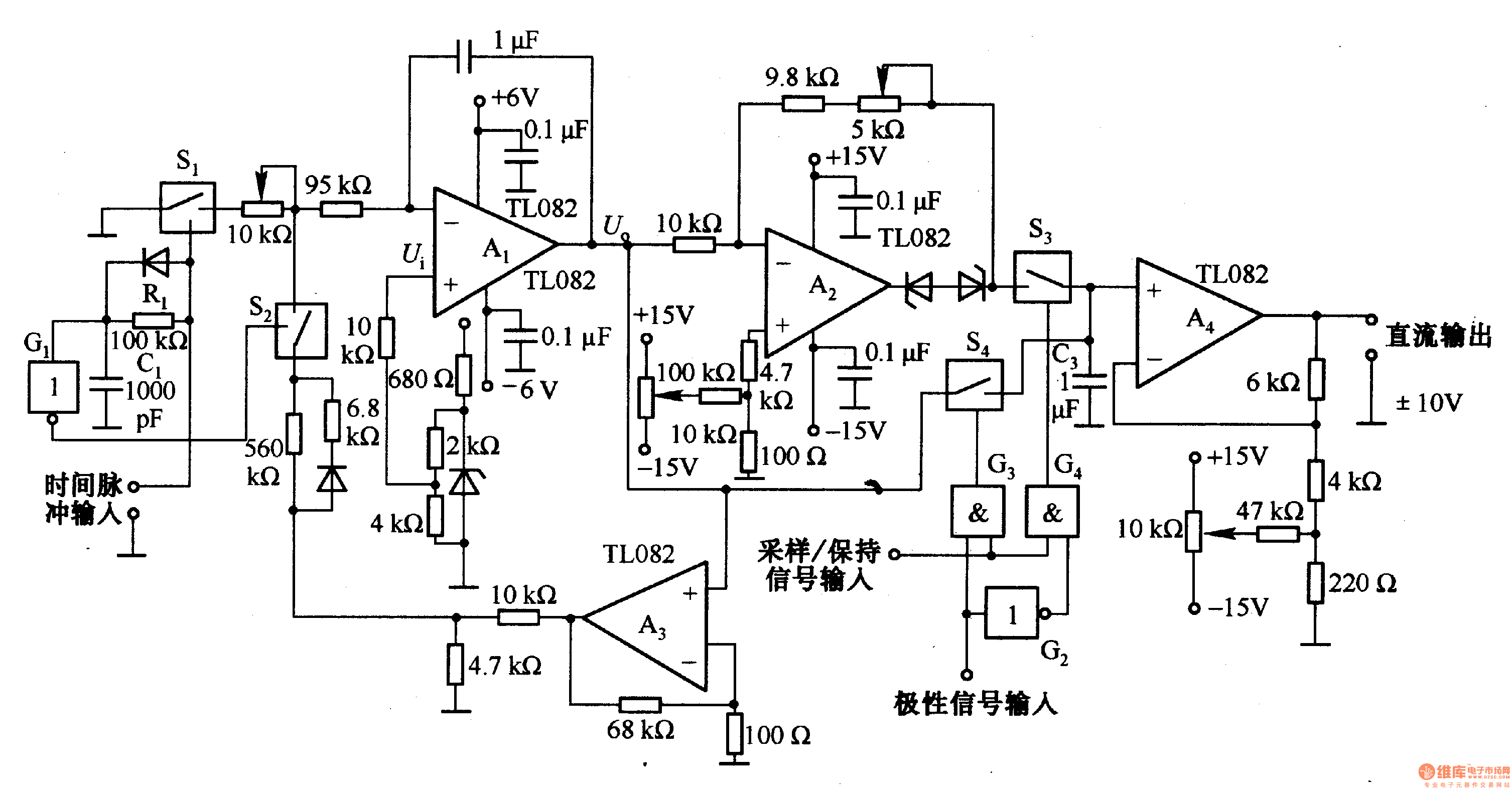
The pulse width to voltage conversion circuit operates on the principle of integrating a reference voltage over a specified time interval defined by the input pulse width. The core component of this circuit is the operational amplifier configured as an integrator (A1). The integration process begins when the input pulse is detected, which activates the appropriate switches (S1 and S2) to control the feedback loop.
Initially, when a pulse width of 0.1 seconds is applied, S1 is opened, and S2 is closed, resulting in an output of 0V from the integrator. This state is stable until the input pulse is increased. Once a new pulse is detected, S1 closes, allowing the feedback loop to engage while S2 opens. The integrator then starts to accumulate the reference voltage, which is typically set to a predetermined value that will yield the desired output voltage of 10V after the integration period.
As the integrator processes the input pulse, the output voltage decreases in the negative direction due to the nature of the integration operation. The output will reach a low level once the integration period concludes, indicating that the pulse width has been fully processed. If the input pulse subsequently drops to a low state, S1 is immediately opened, halting the integration process and returning the circuit to its initial state.
This circuit is particularly useful in applications where precise voltage control based on pulse width modulation is required, such as in motor speed control, signal processing, or in digital-to-analog conversion systems. The careful selection of component values, including the resistors and capacitors associated with the integrator, will directly influence the accuracy and responsiveness of the output voltage to changes in pulse width.This is the pulse width (time) / voltage conversion circuit, according to the diagram component parameters, it can convert 0. 1 S pulse width into 10V output voltage. When time pulse input end is added input conversion pulse, the analog switch Sl is disconnected, and S2 is connected, then Al integrator output is OV.
This state has been maintained t o be increased the input pulse. After added pulse, Sl is turned on and S2 is off, and the feedback loop is cut off, then Al makes integral on the reference voltage, and its output reduces in the negative direction and changes into low level at the end of integral. If the input pulse goes low, Sl is immediately disconnected. 🔗 External reference
Related Circuits
Zilog's Z8 Encore XP F1680 Series features a highly optimized set of capabilities specifically designed for stepper motor microstepping control. Key features of the Z8 Encore! XP F1680 include: an 11 MHz internal oscillator, two analog comparators, a 10-bit...
A remote control light switch designed to fit into an existing light switch panel requires a 3.3V DC power supply for its electronics. However, the panel contains only two wires: one live wire and one wire that connects to...
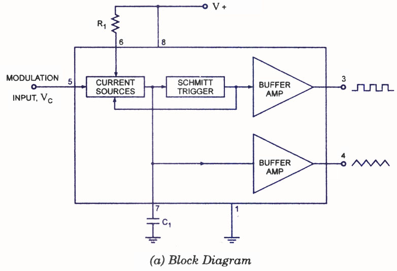
A voltage-controlled oscillator (VCO) is a type of oscillator in which the frequency of output oscillations can be adjusted by varying the amplitude of an input voltage signal. VCOs are commonly utilized in frequency modulation (FM), pulse modulation (PM),...
This is a pressure sensor signal conditioning circuit. It is a simple and inexpensive circuit due to its small geometry and the use of a straightforward pressure sensor. The pressure sensor signal conditioning circuit is designed to convert the raw...
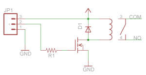
Before proceeding with the toaster oven reflow oven project, it is essential to understand the operation of relays and how to construct a simple relay breakout board. This discussion will focus on the design of a relay breakout board...
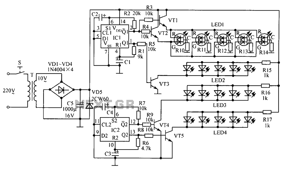
The electronic components designed by conventional electronic bonsai create a sparkling and brilliant atmosphere in the living room, enhancing the joys and pleasures of life. The selection of components includes IC1 to IC4, which consist of two pairs of...