
Relay Circuit and Breakout Board
Relays consist of a coil (essentially an inductor) that activates a magnetic switch; when current flows through the coil, the relay engages. It is crucial to note that relays will not activate until a specific current flows through the coil, which often exceeds the output capability of a microcontroller, necessitating the use of a transistor to amplify the current. The first step in selecting a relay is determining the maximum current and voltage it will control. For the toaster oven, which has a maximum power rating of 1500W at 120V, the maximum current can be calculated using the formula: power = current × voltage. This results in a maximum current requirement of 12.5A, but it is advisable to design for 15A for safety. Additionally, the coil voltage and activation current must be established. Since relays that operate at 3.3V or lower can be costly, a relay with a 5V coil voltage will be used, compatible with 5V microcontrollers. The selected relay has an operating power of 380mW and requires a minimum current of 76mA to activate. Given that this exceeds the current output of a microcontroller pin, a transistor circuit will be necessary. The chosen relay also features #250 tab terminals, simplifying connections. The relay output will function as a switch, connecting the heating elements to the AC return path.
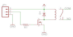
For a comprehensive design, the relay breakout board should include the relay, a transistor for current amplification, and any necessary resistors or capacitors to ensure stable operation. The transistor should be chosen based on its ability to handle the relay's coil current while being compatible with the microcontroller's output. A common choice is an NPN transistor, which can be driven by the microcontroller to switch the relay. The base of the transistor will require a resistor to limit current from the microcontroller, typically in the range of 1kΩ to 10kΩ, depending on the transistor's specifications.
The relay should be rated for the maximum voltage and current requirements of the toaster oven, ensuring that it can handle the load safely. The relay's coil should be connected to the transistor's collector, while the emitter connects to ground. The microcontroller's output pin will connect to the base of the transistor through the resistor, allowing the microcontroller to control the relay.
Additionally, flyback diodes should be included across the relay coil to prevent voltage spikes when the relay is deactivated, protecting the transistor and microcontroller from potential damage. Proper PCB layout and design considerations should be taken into account to minimize interference and ensure reliable operation. Overall, this relay breakout board design will enable effective control of high-power devices while maintaining safety and functionality.Before continuing with our toaster oven reflow oven project, we should understand how relays work and how to build a simple relay breakout board. This post will discuss the design of a relay breakout board specifically for our reflow oven project.
Disclaimer: As I mentioned in the previous post, do not attempt this project unless you know what yo u are doing. High voltages are dangerous and can kill you. Do this project at your own risk! This part is especially dangerous, as we are dealing directly with high voltage signals. The goal of a relay is to control high power devices using low power signals. A perfect example is controlling a 1500W toaster oven with a 3. 3V or 5V microcontroller. Another example would be using a microcontroller to turn on or off lights in your house/apartment/dorm. Although the two examples I just gave involve turning on or off AC power to a device, relays can also switch high power DC signals such as headlights on a car.
While there are many different methods you can use for switching AC devices, I will only mention three of them. The first method uses a triac, the second uses a solid state relay, and the third uses an electromechanical relay.
The first two methods are solid state, which means there are no moving parts; there are many advantages to using these two methods. The downside of using a triac circuit, is that it is not trivial to build. The downside of using a solid state relays is that it can be very expensive compared to electromechanical relays.
For this post, we will focus on electromechanical relays due to how easy they are to use and how inexpensive they are. Check out the Wikipedia page for a more detaileddescriptionof how relays work. To summarize, relays contains a coil (basically an inductor) which either forces a magnetic switch on or off; when current is flowing through the coil, the relay is on .
It is also important to note that relays won`t turn on until a certain amount of current is flowing through the coil. Many times, this current exceeds what a microcontroller can output so a transistor is needed to boost the current going into the coil.
The first thing you need to determine when choosing a relay, is the maximum current and voltage you want the relay to control. For this project, my toaster oven has a maximum rated power of 1500W at 120V. It is important to find your maximumpower, which is typically listed on every device. Using the following equation we can determine the maximum current the relay must switch on and off. This is a very simple, yet useful equation; power is equal to current times voltage. Using this equation, the maximum current we need to design for is 12. 5A. In engineering, it is always important toover-specifyyour system. Despite the fact that we only need to design for a maximum of 12. 5A, we should design for 15A. This is a lot of current, way more than most devices will ever use. It is better to be safe than sorry! Finally, the coil voltage and activation current must be determined. Since relays which can be turned on using a coil voltage of 3. 3V or lower are expensive, we will be using a relay that has a coil voltage of 5V. This is great for those of you using a 5V microcontroller. Now that we know the coil voltage, we must find the cheapest relay which has the lowest turn on current.
For my specific relay, this is denoted as Operate power . Given an operating power of 380mW and a voltage of 5V, the coil requires a minimum current of 76mA to turn on the relay. Since my coil requires more power than a microcontroller pin can drive, a transistor circuit will be needed.
The last thing to note about the relay I have chosen, is that it is available with #250 tab terminals . As I mentioned in the previous post, this will greatly simplify things! The output of the relay simply acts as a switch; for this project it will be hooked up between the heating elements and the AC return path (as
🔗 External reference
Related Circuits
A project of a 555 tester circuit, the circuit will start blinking LEDs when power is applied, which will indicate that the IC is working correctly. The 555 tester circuit is designed to verify the operational status of the 555...
Radio-Circuits has elevated the standard with this website. Unlike any other circuit site on the internet, they have compiled ten of the most popular FM transmitter circuits. Radio-Circuits provides a comprehensive collection of FM transmitter circuits, showcasing a variety of...
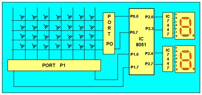
The keyboard being interfaced is a matrix keyboard designed with specific rows and columns. These rows and columns connect to the microcontroller via its ports, specifically the 8051 microcontroller. An 8x8 matrix keyboard is typically used, allowing connection to...
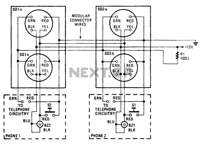
An intercom utilizing dual-modular wall jacks is depicted in this circuit. If the wires are accessible in the home telephone cable, this system can be installed with minimal difficulty. The intercom system described employs dual-modular wall jacks, which are standard...
The ML4423 is an integrated controller designed for single-phase and two-phase AC induction motors. It features PWM (Pulse Width Modulation) capabilities for speed control and includes various protection circuits such as short circuit protection, fire protection, and a reference...
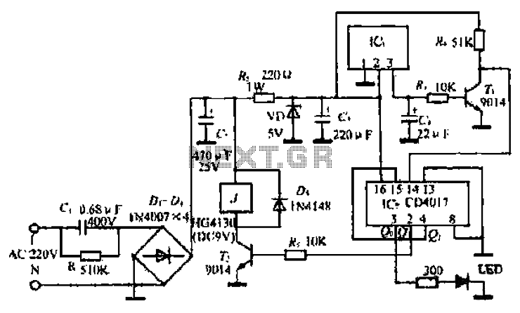
The goal is to create a small light that is activated by motion and stays illuminated for 20 seconds before turning off. For example, when the light is picked up, it illuminates, and when placed back down, it remains...
Warning: include(partials/cookie-banner.php): Failed to open stream: Permission denied in /var/www/html/nextgr/view-circuit.php on line 713
Warning: include(): Failed opening 'partials/cookie-banner.php' for inclusion (include_path='.:/usr/share/php') in /var/www/html/nextgr/view-circuit.php on line 713