
Pulsed Induction Metal Detector

B1 consists of four 3.6 volt Li-ion batteries in series making up a 16.8 volt source when fully charged. These were salvaged from old Sony cell phone battery packs. The average current drawn by PI detectors is usually high because of the power needed to drive the search coil. This circuit draws less than 200 mA, which gives over two hours operation between charges with the cells used. Ni-Cds or Ni-MH can be used but remember to use enough cells to provide at least 15 volts into the regulator. Sealed lead acid batteries would work but they would be pretty heavy, perhaps a belt-worn battery pack.
U1 makes up the entire timebase. It is a programmable divider with built-in oscillator. With a common 3.579545 mHz crystal, several useful frequencies can be obtained by configuring the jumpers at A, B, and C on the circuit board. It also has a one-shot multivibrator which allows setting the pulse width out.
The frequency of operation on a PI detector varies from design to design and from coil to coil on any given design. The higher the frequency, the more power is consumed, so it is necessary to decrease the TX pulse width to compensate until a point in frequency is reached where the pulse becomes too short and performance starts to drop off. A good compromise found through experimentation is between 75 and 225 Hz, with a pulse width of about 100 to 175 microseconds in duration.
With the jumper setting "110" in the schematic, the output frequency is 109.2390442 Hz, which works well with a TX pulse width of 125 microseconds set by R2. Different frequencies can be selected in multiples of 2 by changing the binary code at A, B, and C inputs.
U2 takes the TX pulse and derives the RX pulse and delay which drives U4, the sample circuit. The sample then goes to U5A, a sample and hold circuit that obtains an average DC voltage from the samples. U5 is an all-CMOS device with an output that can swing rail-to-rail. U5B then further amplifies the voltage to obtain a 0 to 12 volt swing which tracks the distance and/or size of the metal object. This DC voltage drives M1 and OC1, an opto-coupler that provides a varying bias to U6, a 555 timer, which produces a ticking sound when an object is first detected, turning into a higher pitched squeal as the object gets closer to the coil. The threshold control is set to a point where the ticking just starts.
The schematic includes a speaker for audio output, but a piezoelectric transducer can be used in its place, eliminating R26. Additionally, a headphone jack is installed on the output to assist in noisy environments.
Parts List:
- B1: 3.6 V Lithium cell x 4 for a fully charged voltage of 16.8 volts.
- D1, D2, D3, D4: 1N4148
- L1: Search coil, 27 turns, 9.5 inches O.D., #20 enameled wire, flat spiral wound.
- M1: 50 µA DC Ammeter
- OC1: 4N35 Opto Coupler
- Q1: IRF740
- Q2: MPSA70 or any general-purpose PNP transistor with a beta of 40 or higher.
- U1: 4536B
- U2: 4538B
- U3: LM318
- U4: 4066B
- U5: ICL7621
- U6: 555
- VR1: LD1085V12 Low dropout 12 volt 3 amp positive regulator
- XTAL1: 3.579545 mHz crystalAs you can see, there is only one regulated 12 volt supply operating the entire circuit. I was able to do this simply by AC coupling the received signal to U3 via C10. This allowed me to adjust the offset within an operating window. By using a tantalum capacitor of reasonably high capacity, the signal passes with no problems. See Waveforms and Adjustments. This met my first goal. The regulator IC is a low dropout type capable of handling 3 amp. loads. This is necessary because the peak current of the TX pulse into the search coil is near 3 amps. and I wanted the circuit to still operate when the battery dropped to 13.5 volts. With the timing I am currently using, this IC doesn't get warm. However, the range of the pots and jumpers allows you to adjust the circuit to a point where Q1 and VR1 will warm up, so I included room for heat sinks on the circuit board so you can experiment without worrying about damaging these parts. B1 consists of four 3.6 volt Li-ion batteries in series making up a 16.8 volt source when fully charged.
These were salvaged from old Sony cell phone battery packs. The average current drawn by PI detectors is usually high because of the power needed to drive the search coil. This circuit draws less than 200 mA. which gives over two hours operation between charges with the cells I used. You can use Ni-Cds or Ni-MH but just remember to use enough cells to provide at least 15 volts into the regulator.
Sealed lead acid batteries would work but they would be pretty heavy, perhaps a belt-worn battery pack. I haven't tried this circuit without a regulator. Maybe someone out there will do some experimenting in this area. Let me know what you come up with for power. U1 makes up the entire timebase. It is a programmable divider with built-in oscillator. With a common 3.579545 mHz. crystal, you can get several useful frequencies out by configuring the jumpers at A,B and C on the circuit board.
It also has a one-shot multivibrator which allows you to set the pulse width out. The frequency of operation on a PI detector varies from design to design and from coil to coil on any given design. Basically, the higher the frequency, the more power is consumed, so you have to decrease the TX pulse width to compensate until you reach a point in frequency where the pulse gets too short and performance starts to drop off.
The same thing happens on the low side of the frequency range, but here, the pulse gets too long to still work and ends up just consuming more power than necessary. I have found by experimenting, that a good compromise is between 75 and 225 Hz. with a pulse width of about 100 to 175 microseconds in duration. Still, this is with the coil I am using. With the jumper setting "110" in the schematic, the frequency out is 109.2390442 Hz. which works well with 125 microseconds for the TX pulse width which is set by R2. You can select different frequencies in multiples of 2 by changing the binary code at A,B and C inputs.
The following table shows the frequencies possible with a 3.579545 mHz. crystal: C B A Frequency 0 0 0 6,991.298828 Hz. 0 0 1 3,495.649414 Hz. 0 1 0 1,747.824707 Hz. 0 1 1 873.91235 Hz. 1 0 0 436.956176 Hz. 1 0 1 218.4780884 Hz. 1 1 0 109.2390442 Hz. 1 1 1 54.61952209 Hz. For more information on this, see the data sheet on the 4536B. You might want to experiment in this area too. Let me know what you find. U2 takes the TX pulse and derives the RX pulse and delay which drives U4 the sample circuit. The sample then goes to U5A which is a sample and hold circuit which obtains an average DC voltage from the samples. U5 is an all-CMOS device that has an output which can swing rail-to-rail. Last time I checked, it was available from Newark, part number 57K3887. If you have trouble getting this part, let me know, I have several of them that I am selling for $ 1.00 each plus postage.
I had a sensitivity control (R14) on the first version I built, but I decided I didn't need it and later replace it with a jumper. Also, I changed R13 to 10 K. U5B then further amplifies the voltage to obtain a 0 to 12 volt swing which tracks the distance and/or size of the metal object.
This DC voltage drives M1 and OC1, an opto-coupler which provides a varying bias to U6 a 555. The 555 produces a ticking sound when an object is first detected then turns into a higher pitched squeal as the object gets closer to the coil. The threshold control is set to a point where the ticking just starts. The schematic shows a speaker for the audio. You can used a piezo electric transducer in it's place and eliminate R26. Also, I installed a headphone jack on the output. This helps in noisy environments. Parts List B1 3.6 v Lithium cell x 4 for a fully charge voltage of 16.8 volts. D1,D2,D3,D4 1N4148 L1 Search coil, 27 turns 9.5 inches O.D.# 20 enameled wire flat spiral wound.
M1 50 uA DC Ammeter OC1 4N35 Opto Coupler Q1 IRF740 Q2 MPSA70 or any general purpose PNP transistor with a beta of 40 or higher. U1 4536B U2 4538B U3 LM318 U4 4066B U5 ICL7621 (See Text) U6 555 VR1 LD1085V12 Low dropout 12 volt 3 amp.
positive regulator (Available from Digi-Key) XTAL1 3.579545 mHz. crystal 🔗 External reference
Related Circuits
This is an infrared (IR) proximity detector circuit. A matched infrared emitter and detector pair is utilized in this circuit. The voltage-controlled oscillator (VCO) section of the LM567 tone detector integrated circuit (IC) is employed to set the emitter...
This circuit will detect AC line currents of about 250 mA or more without making any electrical connections to the line. Current is detected by passing one of the AC lines through an inductive pickup (L1) made with a...
The circuit described is a metal detector. The operation of the circuit is based on the superheterodyne principle, which is commonly used in superheterodyne receivers. The circuit utilizes two RF oscillators, both fixed at a frequency of 5.5 MHz....
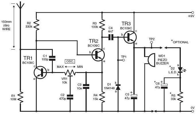
This DIY lightning detector circuit is a highly sensitive static electricity detector that provides an early warning of approaching storms from inter-cloud discharges well before an earth-to-sky return strike occurs. An aerial (antenna) made from a short length of...
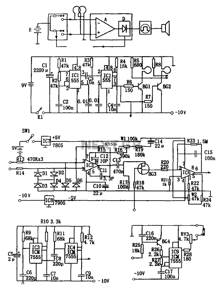
The figure illustrates a double coil metal detector circuit, which consists of a probe, a transmitter, a receiver, a timer, sound transmitters, and other components. The transmitter circuit, depicted in (b), is composed of a multivibrator (IC1, R1, R2,...
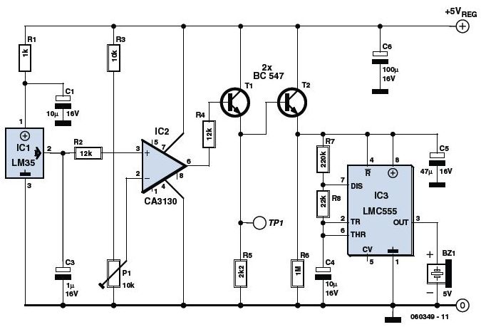
This is an Overheat Detector Alarm Switch using the Temperature Sensor IC LM35. The core of this overheat detector (fire alarm) circuit is a precision integrated temperature sensor, the LM35 (IC1), which provides an accurately linear and directly proportional...