
Pulsed LC Oscillator
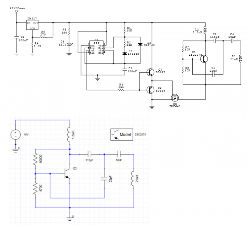
The LC oscillator circuit leverages the properties of inductors and capacitors to produce oscillations at a specific frequency determined by the LC tank circuit. In this configuration, the 555 timer IC operates in astable mode, generating a series of square wave pulses that drive the 2SC2078 transistor. This transistor acts as a switching element, allowing the LC circuit to resonate at its natural frequency.
The resonance frequency of the LC circuit can be calculated using the formula:
\[ f = \frac{1}{2\pi\sqrt{LC}} \]
where \( L \) is the inductance of the coil and \( C \) is the capacitance in the circuit. The measured resonance frequency of 2.74 MHz indicates that the values of inductance and capacitance are appropriately selected to achieve this frequency. The slight difference between the measured and simulated resonance frequencies (2.74 MHz vs. 2.92 MHz) may be attributed to component tolerances, parasitic capacitances, and inductances that are not accounted for in the simulation.
The circuit's operation at 24V DC allows for significant voltage amplification across the coil L2, achieving a peak-to-peak voltage of approximately 800V. This high voltage is indicative of the energy stored in the magnetic field of the inductor during oscillation. The waveform observed in Fig. 3 illustrates the pulsed nature of the output, providing insights into the timing and characteristics of the oscillation, which is crucial for applications requiring precise frequency control.
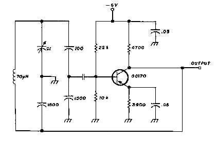
Overall, this LC oscillator circuit demonstrates effective pulse generation and resonance characteristics, making it suitable for various electronic applications, including RF transmission and signal generation.An LC oscillator is driven by pulses which are generated by a 555 IC based oscillator. LC oscillator is built around 2SC2078. The circuit is shown in Fig. 1. The circuit and the Ansoft Designer simulation. Measured and simulated resonance frequencies are 2.74 MHz and 2.92 MHz, respectively.
Fig. 2. Photo of the circuit. Larger coil is L2. When the circuit is fed by 24VDC, peak-to-peak voltage across L2 is about 800V. Fig. 3. Pulsed operation and the waveform in each pulse. Oscillation frequency is 2.74 MHz . By 4beowulf7 - [email protected]
🔗 External referenceRelated Circuits

Almost any transistor will work. R1 and C1 will vary the tone. The circuit utilizes a transistor as the primary active component, which can be substituted with various types of transistors, including bipolar junction transistors (BJTs) or field-effect transistors (FETs)....
An attempt has been made to follow an instructable for some time; however, understanding its schematic remains challenging. The issue is not a lack of knowledge regarding the symbols used. In electronic schematics, symbols represent various components and their connections...
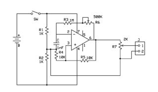
This generally results in a square wave if the frequency of oscillation is low enough relative to the amplifier's bandwidth. The schematic of a crystal-controlled oscillator features a low-frequency sine wave oscillator characterized by low distortion, wideband operation, and...
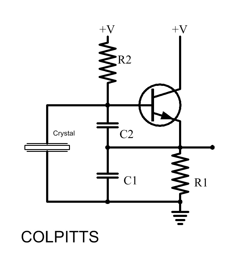
Inquiries about selecting the L, C, and R values to achieve a desired frequency are common. It is essential to understand the relationship between these components and the frequency they produce. The desired frequency can be calculated using the...
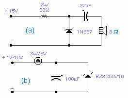
These two circuits are interesting from an academic point of view. Their practical implementation is rather critical and it is not easy to get steady operation. Circuit (a) requires a "cooked" zener: connect it first to a constant current...
The Vackar configuration is recognized as one of the most stable VFO oscillators available. However, its usage is limited due to the NIH (not-invented-here) syndrome. This oscillator offers a frequency tuning range exceeding 2.5, a feature not typically found...