
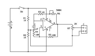
Square wave oscillator
In electronic schematics, symbols represent various components and their connections within a circuit. A comprehensive understanding of these symbols and their functions is crucial for interpreting circuit diagrams effectively. Common symbols include resistors, capacitors, transistors, diodes, and integrated circuits, each serving a specific purpose in the overall design.
To facilitate understanding, it is essential to familiarize oneself with the standard symbols and their corresponding values. For instance, resistors are typically depicted as zigzag lines, while capacitors are represented by two parallel lines. Transistors can be more complex, often shown with additional connections indicating their type (NPN or PNP for bipolar junction transistors, for example).
In addition to symbols, recognizing the layout of the schematic is vital. Components are usually connected by lines that indicate electrical connections, and the arrangement often reflects the flow of current through the circuit. Understanding the function of each component within the context of the circuit is necessary to grasp how they interact to achieve the desired performance.
For those struggling with a specific schematic, it may be beneficial to break it down into smaller sections, analyzing each component and its role individually before considering the circuit as a whole. Utilizing resources such as online tutorials or reference books on electronics can also provide valuable insights into reading and interpreting schematics effectively.Well, I try to follow an instructable for quiet a while now, but I still couldn`t understand its schematic.. its not that I don`t know what the symbo.. 🔗 External reference
Related Circuits
The circuit consists of two oscillators, both working at about 465 kHz. One uses an if transformer and the other uses an inductor (the search coil LI). The oscillators are coupled by a capacitor (10 pF). A beat note...
The single-813 crystal oscillator transmitter, designed by RCA, was showcased in an advertisement on the back page of a 1938 "QST" magazine and published in the RCA HamTips bulletin, volume 1, number 4, dated December 1938. This transmitter delivers...
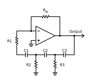
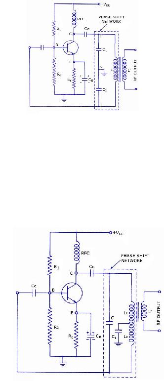
Phase-shift oscillator. An oscillator in which a network has a phase shift of 180 degrees. A phase-shift oscillator is a type of electronic oscillator that generates a sinusoidal output signal. It typically consists of an amplifier and a phase-shifting network...
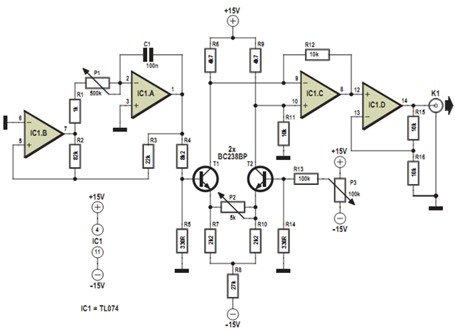
This design was developed to partially replace the well-known 8038 chip, which is no longer in production and therefore difficult to obtain. An existing design for driving a Linear Variable Differential Transformer (LVDT) sensor utilized the 8038 as a...
This report provides details on the principles and operation of an amplifier known as the Wien Bridge Oscillator. The oscillator was designed as part of a laboratory exercise, which was not attended, thus this document will focus on the...
The circuit consists of a lag comparator with amplifier A1 and an inverting integrator A2. The charging and discharging time constant is determined by the integral resistors (R1 + RP1) and the capacitor C1. Diodes VD1 to VD5 form...