
Push-on-push-off electronic switch
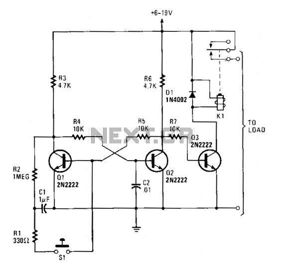
With the inclusion of C2 in the circuit, it and resistor R4 create an RC network that introduces a slight delay in the increase of Q2's base voltage. This delay allows Q1 adequate time to reach saturation and establish control over the circuit.
The described circuit employs two bipolar junction transistors (BJTs) configured as a bistable multivibrator, commonly referred to as a flip-flop. The operation is initiated by the momentary closure of switch S1, which effectively alters the state of the flip-flop. The use of capacitors C1 and C2 is crucial for maintaining stability during power application, ensuring that Q1 remains in a conducting state initially.
The RC time constant formed by C2 and R4 is critical in determining the timing characteristics of the flip-flop. As the voltage across C2 rises, it influences the base of Q2, allowing for a controlled transition from the initial state to the stable state. This timing mechanism prevents rapid oscillations and ensures that the flip-flop can reliably switch states with each actuation of S1.
The relay K1, driven by Q3, provides a practical output for the flip-flop, enabling it to control larger loads. The design's simplicity, along with the inherent properties of the transistors and passive components, allows for a robust solution in applications requiring state retention and toggling functionality.
Overall, this circuit design exemplifies fundamental principles of digital electronics, where transistors act as switches to manage the flow of current, enabling various applications in control systems, memory storage, and signal processing.Transistors Ql and Q2 make up the flip-flop while Q3 drives a reed relay. When power is first applied to the circuit, Ql and Q3 are conducting and Q2 is cut off. Momentarily closing SI causes the flip-flop to switch states—Ql cuts off and Q2 conducts. When Q2 is conducting, its collector drops to around 0.6 volt. That prevents base current from flowing into Q3 so it is cut off, de-energizing relay Kl. The flip-flop changes state every time SI is pressed. Capacitors Cl and C2 ensure that Ql is always the transistor that turns on when power is first applied to the circuit. When power is first applied to the basic flip-flop, the initial status is random—Ql and Q2 both try to conduct and, usually, the transistor with the higher gain will take control, reaching full conduction and cutting off the other one.
However, differences in the values of the collector and coupling resistors will also influence the initial state at power-on. With C2 in the circuit, it and R4 form an R-C network that slightly delays the rise in Q2's base voltage. That gives Ql sufficient time to reach saturation and thus take control. 🔗 External reference
Related Circuits
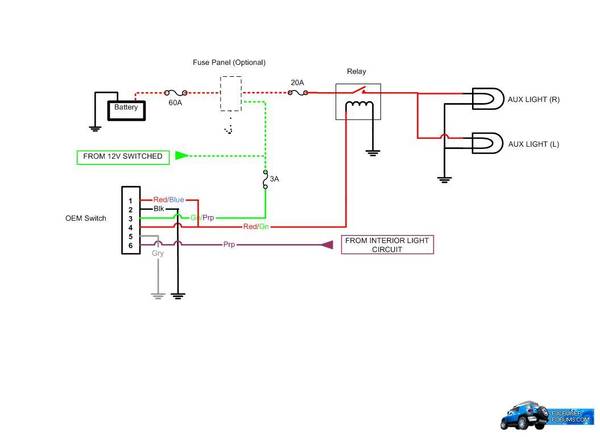
A schematic has been created to illustrate how the OEM AUX switch should be wired, providing a reference for installation. The switch pin layout is labeled for clarity when viewed from the terminals, with the locking tabs on the...
This light sensor switch circuit enables the automatic activation of a lamp when ambient light levels decrease, such as during nightfall. The duration for which the lamp remains on can be adjusted using potentiometer P1, with a range of...
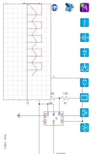
A compilation of the best free Android applications for electronics and electrical engineers, including simulators, resistor color code tools, and electronic toolkits. The compilation of Android applications for electronics and electrical engineers serves as a valuable resource for professionals and...
Speaker relay delay controlling circuit for audio amplifier The speaker relay delay controlling circuit is designed to manage the connection between an audio amplifier and the connected speakers, ensuring that the speakers are activated only after a predetermined delay. This...

The circuit below is similar to the one above but can be used with a laser pointer to toggle the relay rather than a push button. The IR photo transistor Q1 (Radio Shack 276-145A) or similar is connected to...
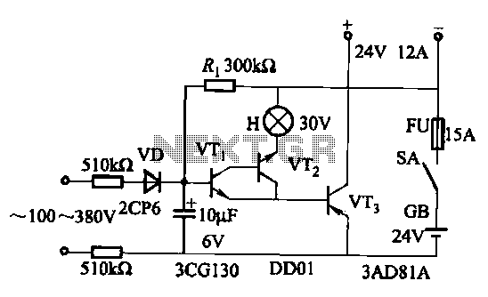
An AC-DC power supply without a power switching circuit is typically employed in lighting load circuits. When the power grid is restored, the standby power supply automatically switches on. The automatic switching circuit utilizes a transistor, as illustrated. The...