
Remote switching with Laser Pointer

The circuit operates as a laser-activated relay toggle mechanism, utilizing an infrared (IR) photo transistor, designated as Q1, which is sensitive to light emitted from a laser pointer. The configuration allows for the relay to be activated without physical contact, enhancing usability in various applications.
In the idle state, the voltage at the set input (pin 6) remains below 1 volt, ensuring that the relay remains off. When the laser pointer illuminates the photo transistor, the voltage at pin 6 rises above 10 volts, triggering the relay to close and activate the connected load. Shielding the photo transistor from ambient light is crucial to prevent unintended activations due to stray light sources.
The circuit includes a 4.7uF capacitor that plays a vital role in controlling the reset time of the relay. This capacitor prevents the circuit from toggling more than once within a half-second interval, providing stability and preventing rapid on-off cycling that could lead to relay damage or erratic behavior. The presence of a 10K resistor and a diode facilitates a faster discharge path for the capacitor, allowing the circuit to be retoggled within one second after the initial activation.
The adjustment of the 3K resistor in series with the photo transistor is essential for optimizing the sensitivity and performance of the circuit. This component can be fine-tuned to ensure reliable operation under varying light conditions and distances from the laser pointer.
The relay used in this circuit can be a solid-state type, which is suitable for controlling resistive loads up to 3 amps, making it ideal for applications such as lighting control. Alternatively, a mechanical relay can be employed, as previously indicated in similar circuit designs, depending on the specific requirements of the application. Overall, this circuit design provides a versatile and effective solution for remote relay activation using a laser pointer.The circuit below is similar to the one above but can be used with a laser pointer to toggle the relay rather than a push button. The IR photo transistor Q1 (Radio Shack 276-145A) or similar is connected to the set input (pin 6). The photo transistor should be shielded from direct light so that the voltage at the set input (pin 6) is less than 1 volt under ambient conditions and moves to more than 10 volts when illuminated by the laser pointer or other light source.
The reset time is about a half second using a 4.7uF cap which prevents the circuit from toggling more than once during a half second interval. The 10K resistor and diode provide a faster discharge path for the 4.7uF cap so the circuit can be retoggled in less than 1 second. The 3K resistor in series with the photo transistor may need be adjusted for best performance. The relay shown is a solid state variety to be used with lights or other resistive loads at less than 3 amps.
A mechanical relay can also be used as shown in circuit above. 🔗 External reference
Related Circuits
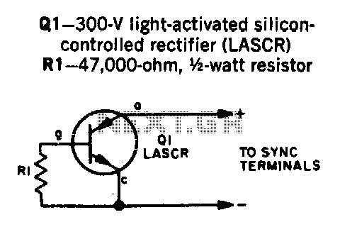
Transistor Q1 is a light-activated silicon-controlled rectifier (LASCR). The gate is activated by light entering a small lens integrated into the top cap. To operate, provide a 6-inch length of stiff wire for the anode and cathode connections, and...
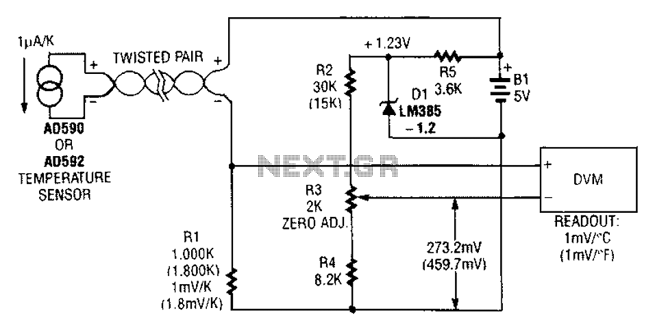
An AD590 or AD592 can be utilized in a transmission line for temperature data transmission. The circuit generates a value of 1 mV per degree Fahrenheit. The AD590 and AD592 are precision temperature sensors that output a voltage proportional to...

The CS3843 and CS5101 are components of a 5V/3.3V switching DC power supply circuit. The CS3843 is a fixed frequency PWM controller characterized by a set oscillator that precisely controls the duty cycle. It features a temperature-compensated reference voltage,...
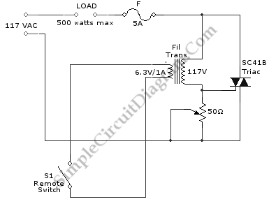
This is a remote on-off switch circuit. This circuit allows the use of a small switch to control larger AC currents from high-power devices. The remote on-off switch circuit operates by utilizing a low-power control signal to manage a high-power...
This article presents basic circuits for pulsing infrared LEDs and low-power visible semiconductor lasers utilizing inexpensive and readily available components. Numerous interesting and practical applications are referenced, alongside several online resources. The focus of the article is on the...

This chapter provides detailed schematics of various power supplies suitable for use with common Ar/Kr ion tubes available to hobbyists in the surplus market. Included are examples of commercial designs (Omnichrome 150R and 532 head, Lexel 88 and head)...