
Light sensor switch circuit
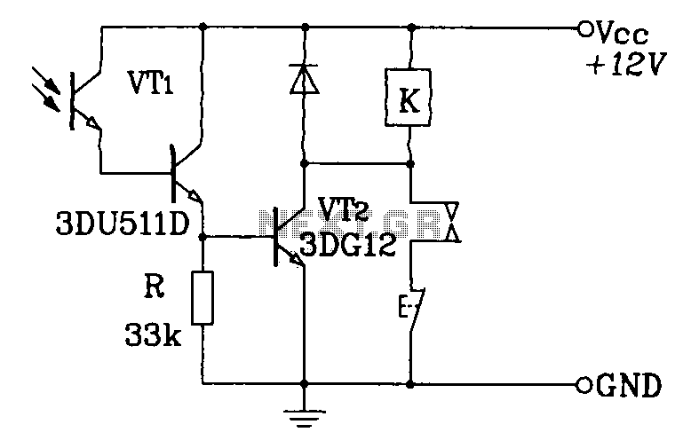
The light sensor switch circuit typically employs a light-dependent resistor (LDR) to detect ambient light levels. When the light intensity falls below a predetermined threshold, the LDR's resistance increases, triggering a transistor or relay to close the circuit and turn on the lamp.
The circuit consists of several key components: the LDR, a potentiometer (P1) for time adjustment, a timing capacitor, and a resistor to set the timing interval. The timing capacitor, in conjunction with the resistor, determines how long the lamp stays illuminated after the LDR detects low light levels.
When designing the circuit, it is essential to select an appropriate transistor or relay that can handle the lamp's load. The output stage is typically connected to the lamp via a relay to ensure safe operation, especially if the lamp operates at mains voltage.
To enhance the functionality of the circuit, a diode can be included across the relay coil to protect against back EMF when the relay is switched off. Additionally, an LED indicator may be added to show when the circuit is active, providing a visual confirmation of operation.
Overall, this light sensor switch circuit is a practical solution for automating lighting in response to changing ambient light conditions, making it suitable for outdoor lighting, garden lights, or any application where automatic light control is desired.This light sensor switch circuit allows the automatic connection of a lamp when the light is low (at nightfall) and will maintain the lamp ON for a certain period of time. This time can be adjusted with P1 between 1 and 5 hours. The switch.. 🔗 External reference
Related Circuits
A recent thrift shopping experience revealed a toy that appears to be suitable for circuit bending. The toy was found without batteries, preventing any testing at the store. It may be beneficial to bring batteries during future visits or...
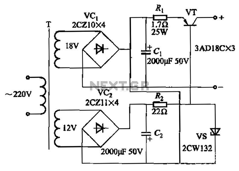
Characterized by a steady flow of power when the power supply voltage fluctuates or the load changes, this circuit maintains a constant load current. The output current of the circuit is illustrated in Figure 4A. When the load varies...
A Darlington phototransistor serves as the primary component for the photoelectric function within a self-locking control relay circuit. The circuit utilizes a Darlington phototransistor, which is known for its high current gain and sensitivity to light. This device is configured...
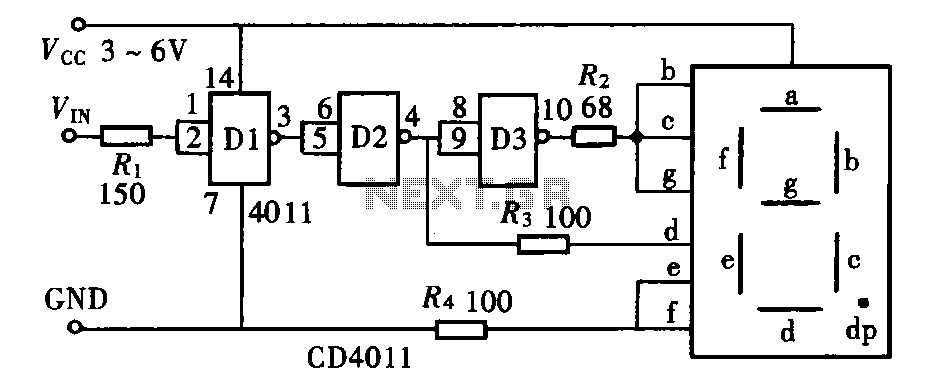
The door circuit logic pen text display can take many forms, utilizing various logic gates such as inverters, NAND gates, NOR gates, and others. A logical pen, exemplified by the NAND gate CD4011, can be used in conjunction with...
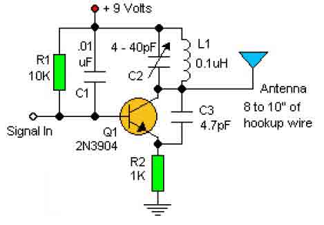
This basic RF oscillator circuit is easy to build and the components are not critical. Most of them can be found in your junk parts box. The L1 antenna coil can be made by close winding 8 to 10...
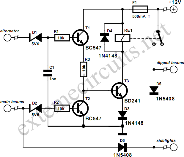
This circuit ensures that the car's lights will automatically activate when the engine is running, preventing the driver from forgetting to turn them on. The dipped beams and sidelights are engaged automatically, while the dipped beams turn off when...