
stepper motor controller using pic16f628a
In the context of electronic schematics, the pursuit of employment can be likened to the systematic design and implementation of a circuit. The process begins with defining the requirements and specifications, similar to setting career goals. Each component in the circuit serves a specific function, just as skills and experiences contribute to professional development.
For instance, consider a basic operational amplifier (op-amp) circuit. The op-amp can be configured in various ways, such as inverting, non-inverting, or as a comparator, depending on the desired output. The selection of resistors, capacitors, and power supply must align with the intended application, mirroring the careful selection of job opportunities based on individual qualifications and aspirations.
The power supply in the circuit is essential, providing the necessary voltage and current for operation. This is akin to the foundational knowledge and training acquired during academic pursuits, which energizes the job search process. The feedback loop in an op-amp circuit ensures stability and accuracy, paralleling the iterative nature of job applications and interviews, where feedback leads to improvements and adjustments in approach.
In conclusion, the design and optimization of electronic circuits involve careful planning, component selection, and iterative refinement, much like the journey of seeking employment after completing a degree. Each step is crucial in achieving the end goal of a successful and fulfilling career.Since I finished my degree in April, I have been looking for work. The search has been slow but hopefully soon I will be making the big bucks. To fill my s.. 🔗 External reference
Related Circuits
The TPS6420x controller is designed to operate from one to three series-connected cells or from a 3.3 V or 5 V supply obtained from a USB port. At its output, it can produce 3.3 V at 2 A, suitable...
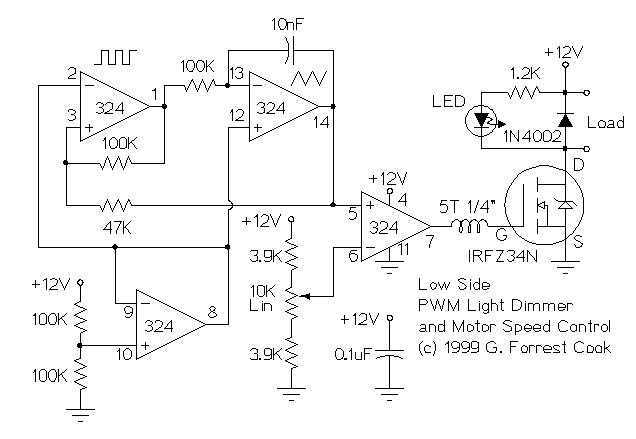
These two schematics are variations on another PWM circuit that I designed. The diagrams are for 12V operation only and there are high side (common ground) and low side (common +12V) versions. The low side version of the circuit...
When the touch switch SI is activated, resistor R4 is driven high, causing the control voltage to rise, which latches the switch. Conversely, when switch S2 is activated, resistor R4 goes low, resulting in a decrease in the control...
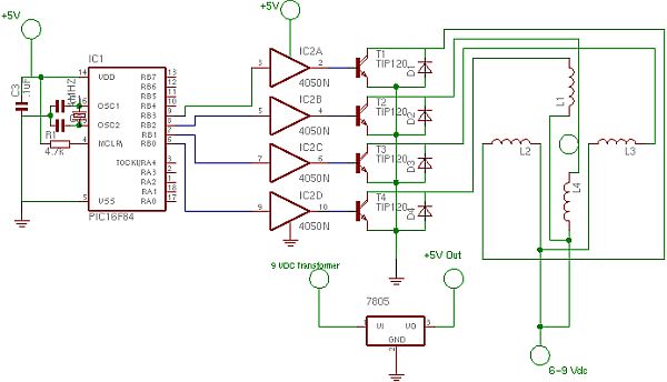
The schematic illustrates the electronics needed to control a stepper motor. It primarily consists of three commonly available integrated circuits and four power transistors for complete motor control. Four PNP power transistors amplify the weak electronic signals into sufficient...
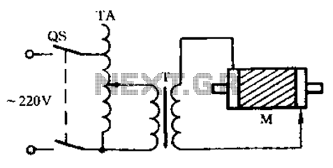
Check the three-phase motor with broken bars as shown in the inspection circuit for the three-phase motor with broken bars. The inspection circuit for a three-phase motor with broken bars is designed to diagnose and evaluate the condition of the...
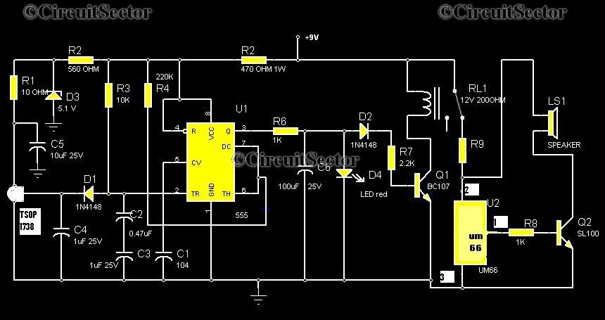
Numerous circuits are available for infrared burglar alarms; however, the transmitter section of these circuits can be complex and may require assembly. This burglar alarm circuit utilizes a standard DVD remote as the transmitter, which reduces both cost and...