
Simple Temperature Controller
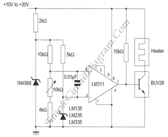
The temperature controller circuit is centered around the LM135/235/335 series of temperature sensors, which are precision devices capable of measuring temperature with high accuracy. The LM135, LM235, and LM335 differ primarily in their temperature range and output characteristics, allowing for flexibility in application depending on the specific requirements.
The circuit typically consists of the temperature sensor connected to an operational amplifier (op-amp) configured as a comparator. The op-amp compares the voltage output from the temperature sensor with a reference voltage, which can be adjusted to set the desired temperature threshold. When the temperature falls below this threshold, the op-amp output switches states, activating a relay or a solid-state switch to turn on a heating element.
Additional components may include resistors and capacitors for signal conditioning and stability, ensuring that the op-amp operates correctly within its linear region. A diode may be included for protection against back EMF if an inductive load, such as a relay, is used.
The power supply for the circuit should be stable, providing the necessary voltage for the sensor and the op-amp, typically in the range of 5V to 15V, depending on the configuration. The LM135/235/335 series sensors can operate over a wide range of temperatures, making them suitable for various applications, including greenhouses, incubators, and temperature-controlled storage.
In summary, the temperature controller circuit using the LM135/235/335 temperature sensor offers a reliable solution for maintaining a desired temperature in a controlled environment. The schematic diagram provides a visual representation of the connections and components involved in the circuit, aiding in the implementation and troubleshooting of the design.This temperature controller employs an LM135/235/335 temperature sensor, can be used to keep small environment warm or hot. Here is the schematic diagram:.. 🔗 External reference
Related Circuits
The sustain pedal, also known as the damper pedal, sends a controller value of CC64 when operated. Pressing the pedal results in an output value of 127, while releasing it results in an output value of 0. Tone generators...
Transistors Q1 and Q2, along with resistors R1 through R7, form the input balancing stage that measures the resistance between points X and Y. This stage operates as a bridge circuit, incorporating resistors R1, R2, R6, R7, and the...
The A3952S stepper motor controller, designed by Allegro MicroSystems, can be utilized to create a straightforward and effective motor driver circuit suitable for various electronic applications. This controller supports continuous output currents of up to 2 A and operates...
Over-Temperature Alarm Circuit Uses Common, Inexpensive Components | Negative-temperature-coefficient (NTC) thermistor, ICs. The Over-Temperature Alarm Circuit is designed to detect excessive temperatures and provide an alert using readily available and cost-effective components. The core sensing element of this circuit is...
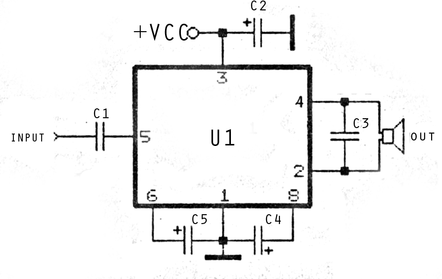
The image above depicts a miniature audio amplifier that is quite simple in design. A schematic for this audio amplifier is provided, which requires only a few components, as detailed in the accompanying diagram. This amplifier is inexpensive to...
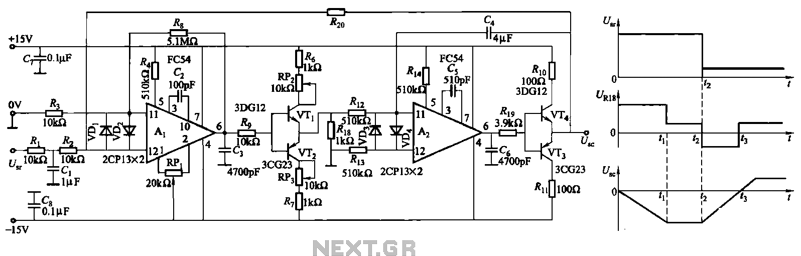
The ZKJ-S-type buffer controller circuit is designed for motor starting slip control. This buffer controller is composed of two operational amplifiers, Ai and Az. The operational amplifier Ai functions as a speed amplifier that saturates, while Az acts as...
Warning: include(partials/cookie-banner.php): Failed to open stream: Permission denied in /var/www/html/nextgr/view-circuit.php on line 713
Warning: include(): Failed opening 'partials/cookie-banner.php' for inclusion (include_path='.:/usr/share/php') in /var/www/html/nextgr/view-circuit.php on line 713