
PWM Generator
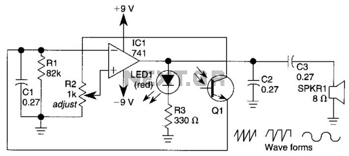
The circuit operates on the principle of pulse-width modulation, where the duty cycle of the PWM signal is directly influenced by the input voltage from the DAC. The triangle wave generator produces a continuous triangular waveform, which is compared against the DAC output voltage by the comparator. The comparator's output toggles between high and low states based on the relationship between the triangle wave and the DAC output.
When the triangle wave voltage (Vtriangle) rises above the DAC output voltage (Vdac), the comparator outputs a low signal, effectively turning on the output transistor, allowing current to flow through the LED. Conversely, when the triangle wave voltage falls below the DAC output, the comparator outputs a high signal, turning off the transistor and cutting off current to the LED. This switching behavior results in a PWM signal that modulates the LED's brightness based on the DAC's output voltage.
The duty cycle of the PWM signal can be calculated as the ratio of the time the output is high to the total period of the triangle wave. As the DAC output increases, the time the triangle wave is above this voltage increases, resulting in a higher duty cycle and a brighter LED. Conversely, a lower DAC output results in a shorter high state duration, leading to a dimmer LED.
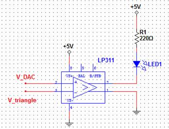
The circuit can be simulated using SPICE to visualize the effects of varying the DAC output on the LED brightness. By observing the two different Vdac values in the simulation, one can gain insight into the relationship between the DAC output voltage and the resulting PWM signal characteristics. This setup serves as an effective demonstration of PWM principles and their application in controlling LED brightness.Using a triangle wave and a comparator, a pulse-width modulated signal can be created. We will use the DAC as our input signal and the resulting output signal will have a duty cycle that is proportional to the input voltage. We will then use the PWM signal to dim an LED. Build the circuit shown in Schematic 1 below. Hook up the triangle wave gener ator to the node labeled Vtriangle and the output of the DAC to the node labeled Vdac. Play around with the bits of the DAC and observe how the brightness of the LED changes. Try plugging Vdac and Vtriangle into the oscilloscope and observe them as the bits on the DAC are changed. If the triangle signal is not working properly, the function generator can be used instead. Open the function generator by clicking the FGEN icon on the instrument launcher. Change the waveform settings to be a Triangle output, 2. 53 kHz, 3. 60 Vpp, and 1. 52 V DC offset. Just like the comparator circuit from the triangle wave generator, when the positive input is lower than the negative, the output will be low.
Therefore, when Vtriangle is greater than Vdac, the output is low. When the output is low, the output transistor looks like a short circuit. The forward diode voltage for a yellow LED is approximately 2V. Thus, the current through the LED can be calculated as: When V triangle is greater than Vdac, the output is high. In the case of the LP311, when the output is high, this translates to the output transistor being off, which looks like an open circuit.
If the output transistor looks like an open circuit, then no current can flow through the LED, and therefore the LED is off. Since the triangle wave is periodic and the DAC output voltage is fixed at a DC level, the current through the LED will be a square wave with a duty cycle that is proportional to the DC level.
Higher DAC output voltage will result in a higher current duty cycle, which will make the LED brighter. Lower DAC output voltage will result in a lower current duty cycle, which will make the LED dimmer. The SPICE simulation results are shown below. Two values of Vdac are shown in the simulation for better understanding of the operation of the circuit.
🔗 External reference
Related Circuits
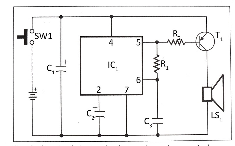
This document presents a verified circuit diagram for a simple, interesting, and cost-effective electronic clapper (sound generator) circuit, along with a description of its functionality. The electronic clapper circuit is designed to activate sound generation through the detection of sound...
The interval between rings can be adjusted by changing the value of the 1 Meg resistor. A 70 volt, 30 Hz ringing voltage is generated from the 120 volt side of a small 12.6 VAC power transformer (Radio Shack...
A basic square wave generator has been designed to operate a speedometer circuit board, which is responsible for controlling various functions. The square wave generator circuit typically consists of a few key components: a timer IC, such as the 555...

Building a signal generator is an essential project for any analog DIY enthusiast. While already possessing a bench signal generator, the intention was to create a compact, battery-powered device for quickly testing new effect designs. An enclosure from a...
A 555 timer operating in astable mode generates driving pulses, while two 4518 dual BCD (binary coded decimal) counters provide square waves. A TL081 operational amplifier functions as an output buffer-amplifier. Potentiometers R1 and R2 are utilized to control...
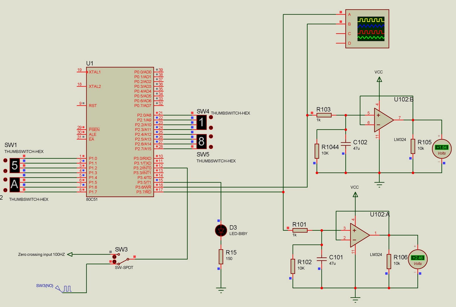
This project currently outputs two PWM signals but can be easily extended to generate multiple PWM signals. The input to the microcontroller consists of 100Hz pulses serving as zero-crossing signals. It is designed for a two-channel DAC, where the...