
PWM Modulator

This circuit is designed to facilitate experimentation with pulse-width modulation (PWM), a technique widely used for controlling power delivered to electrical devices. The simplicity of the circuit allows users, especially beginners, to understand the fundamental principles of PWM without the complexity of advanced circuitry.
The core of the circuit typically involves a microcontroller or a 555 timer IC configured in astable mode. This configuration generates a square wave output, which can be adjusted to vary the duty cycle. The duty cycle determines the proportion of time the signal is high compared to the total period of the waveform, effectively controlling the average power supplied to the load.
In this circuit, a resistor-capacitor (RC) network is employed to set the frequency of the PWM signal. The values of the resistor and capacitor can be modified to achieve the desired frequency range. An output transistor may be included to drive larger loads, allowing the circuit to control devices such as motors or LEDs without overloading the microcontroller or timer IC.
Additionally, a feedback mechanism can be integrated to refine the PWM signal based on the load's response. This could involve using a potentiometer to adjust the duty cycle manually or employing a sensor to provide real-time feedback for automatic adjustments.
Overall, this PWM circuit serves as an effective educational tool, demonstrating the principles of signal modulation and power control while maintaining a straightforward design that is accessible to individuals with varying levels of experience in electronics.If you ever thought of experimenting with pulse-width modulation, this circuit should get you started nicely. We ve kept simplicity in mind and used a dua.. 🔗 External reference
Related Circuits
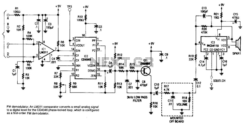
An LM311 comparator converts a small analog signal to a digital level for the DC4046 phase-locked loop, which is configured as a first-order FM demodulator. This demodulator operates with a 50-kHz FM modulated input signal and has applications in...
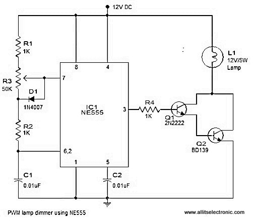
A simple and efficient PWM lamp dimmer utilizing the timer IC NE555 is presented in this article. Traditional linear regulator-based dimmers achieve a maximum efficiency of only 50%, which is significantly lower than PWM-based dimmers that can exceed 90%...
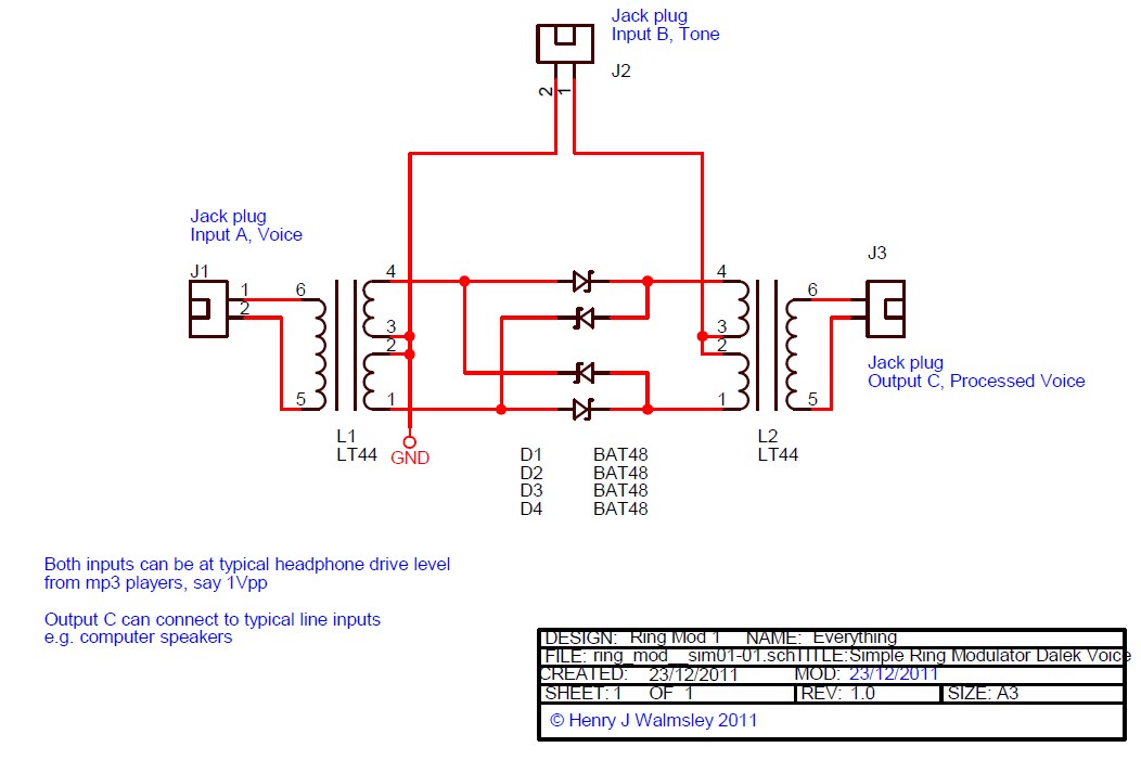
This is a simple ring modulator circuit designed to create interesting analog sound effects using two audio sources and an amplifier or recording device. With the widespread availability of MP3 players and powered computer speakers, building this circuit is...
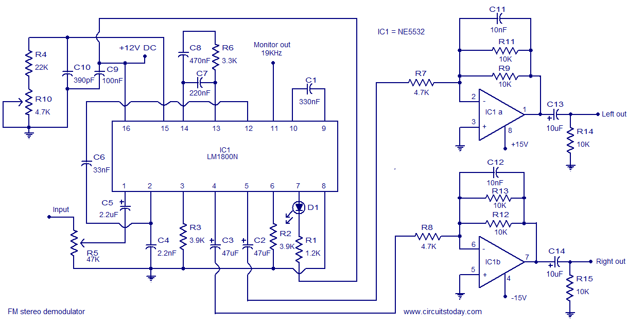
The following circuit illustrates the LM1800 IC Integrated FM Stereo Demodulator Circuit. Features include excellent sound quality and high-quality FM stereo. The LM1800 Integrated Circuit (IC) serves as a highly effective FM stereo demodulator, designed to deliver superior audio performance...
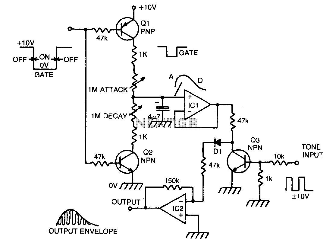
When a gate voltage is applied, Q1 is activated, and capacitor C is charged through the attack potentiometer in series with a 1 KΩ resistor, which varies the attack time constant. A fast attack results in a percussive sound,...
After constructing a Pulse Width Modulator for high-power LEDs, another LED modulator was developed for an optical transceiver. This project utilized a different approach, focusing solely on linear techniques for audio modulation. Similar to the PWM circuit, this circuit...