
PWM motor speed controller
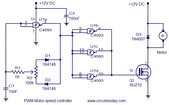
The circuit operates by leveraging the characteristics of the CD4093 Schmitt trigger IC, which provides a stable output even with noisy input signals. The oscillator configuration formed by U1a generates a square wave signal whose frequency and duty cycle can be adjusted by changing the values of the timing components connected to it, typically resistors and capacitors. This square wave output is then buffered by U1b, U1c, and U1d to ensure that it can adequately drive the gate of the MOSFET Q1 without introducing significant signal degradation.
The MOSFET acts as a switch that controls the power delivered to the DC fan motor. When the gate of the MOSFET receives a high signal from the buffered output of the oscillator, it turns on, allowing current to flow through the motor. The speed of the motor is directly proportional to the duty cycle of the PWM signal; a higher duty cycle results in a higher average voltage across the motor, leading to increased speed. Conversely, a lower duty cycle reduces the average voltage and decreases the motor speed.
Diode D3 is crucial for protecting the circuit from back EMF generated by the inductive load of the motor when it is switched off. This back EMF can cause voltage spikes that may damage the MOSFET and other components. D3 allows the current generated by the motor's inductance to circulate safely, preventing damage and ensuring reliable operation.
Overall, this circuit effectively meets the specified requirements for a DC fan motor controller, providing adjustable speed control through a simple and robust design.This circuit is designed as per a request made by Mr Vinoth from India. His requirement was a 12V/5A DC fan motor controller. I think this circuit is sufficient for this purpose. Quad 2 input Schmitt trigger IC CD4093 is the heart of this circuit. Out of the four Schmitt triggers inside the 4093, U1a is wired as an oscillator with adjustable duty cycle. The U1b, U1c, U1d buffers the output of the oscillator to drive the switching MOSFET Q1. The MOSFET drives the DC motor according to the switching pulse obtained from the oscillator. When R1 is varied the duty cycle varies and so do the speed of the motor. Diode D3 acts as a freewheeling diode. 🔗 External reference
Related Circuits
The basic stamp cannot directly power motors due to its maximum current output of only 20mA, while motors typically require around an amp or more, with even higher current spikes. To address this limitation, a circuit will be implemented...
The objective is to transmit additional information by distributing articles. Please contact us via email at [email protected] within 15 days if there are issues related to article content, copyright, or other concerns. We will promptly remove the articles if...
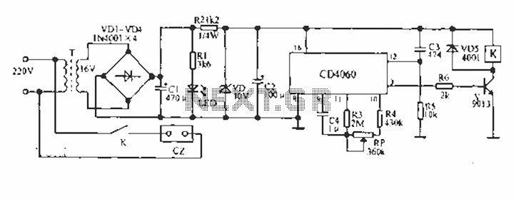
A CD4060 production time controller circuit is illustrated below. It is connected in such a way that R5 and C3 form a differential circuit to create a delay time from the start. Under the influence of the oscillating signal,...
This integrated circuit is highly efficient and does not require any external glue logic for operation. It features two pins to control a motor: one for direction and the other for stepping pulse triggers. The design is compact and...
The circuit described here is for a general purpose device that can control DC devices which draw up to a few amps of current. The circuit may be used in either 12 or 24 Volt systems with only a...
This document outlines the theory behind a high-speed control scheme for an LED display screen circuit. The circuit utilizes the MCS51 series microcontroller to manage the LED display. A 62512 random access memory (RAM) is employed for data storage,...
Warning: include(partials/cookie-banner.php): Failed to open stream: Permission denied in /var/www/html/nextgr/view-circuit.php on line 713
Warning: include(): Failed opening 'partials/cookie-banner.php' for inclusion (include_path='.:/usr/share/php') in /var/www/html/nextgr/view-circuit.php on line 713