
Motor Speed Controller

The circuit is designed to control DC loads, capable of handling currents up to several amps, making it suitable for various applications including automotive lighting and small fan speed control. The operation of the circuit is based on Pulse Width Modulation (PWM), a technique that modulates the width of the pulses in a square wave signal to control the amount of power delivered to the load.
In a typical PWM circuit, the duty cycle, which is the ratio of the on-time to the total time of the cycle, can be adjusted from 0% (fully off) to 100% (fully on). This flexibility allows for precise control over the average power supplied to the connected load. By varying the on-time, users can effectively control the brightness of lights or the speed of motors without the inefficiencies associated with resistive methods of power control.
For implementation in 12V or 24V systems, the circuit requires minimal modifications in the wiring, allowing for easy adaptation to different voltage levels. The PWM signal is typically generated using a microcontroller or a dedicated PWM controller IC, which outputs a square wave signal at a frequency that is suitable for the load type.
Key components of the circuit may include a power MOSFET or transistor to switch the load on and off according to the PWM signal, along with necessary protection components such as diodes to prevent back EMF from inductive loads like motors. Filtering capacitors may also be included to smooth out the PWM signal for applications requiring less noise or flicker, such as lighting.
Overall, this circuit provides an efficient and versatile solution for controlling various DC devices, enhancing functionality while minimizing energy loss.The circuit described here is for a general purpose device that can control DC devices which draw up to a few amps of current. The circuit may be used in either 12 or 24 Volt systems with only a few minor wiring changes. This device has been used to control the brightness of an automotive tail lamp and as a motor speed control for small DC fans of the type used in computer power supplies.
A PWM circuit works by making a square wave with a variable on-to-off ratio, the average on time may be varied from 0 to 100 percent. In this manner, a variable amount of power is transferred to the load. The main advantage of a PWM circuit over a resisti 🔗 External reference
Related Circuits
The liquid level controller circuit comprises a power supply circuit and a level detection control circuit, as illustrated in the accompanying chart. The power supply circuit includes a power switch (S1), a power transformer (T), bridge rectifiers (UR1, UR2),...
This circuit is an ETHERNET controller I use the PIC18F452 and the mikroC C Compiler. I use also the JAVA SCRIPT information you can get from www.w3school.com I Control 8 outputs throw the WEB and transfer time information also....
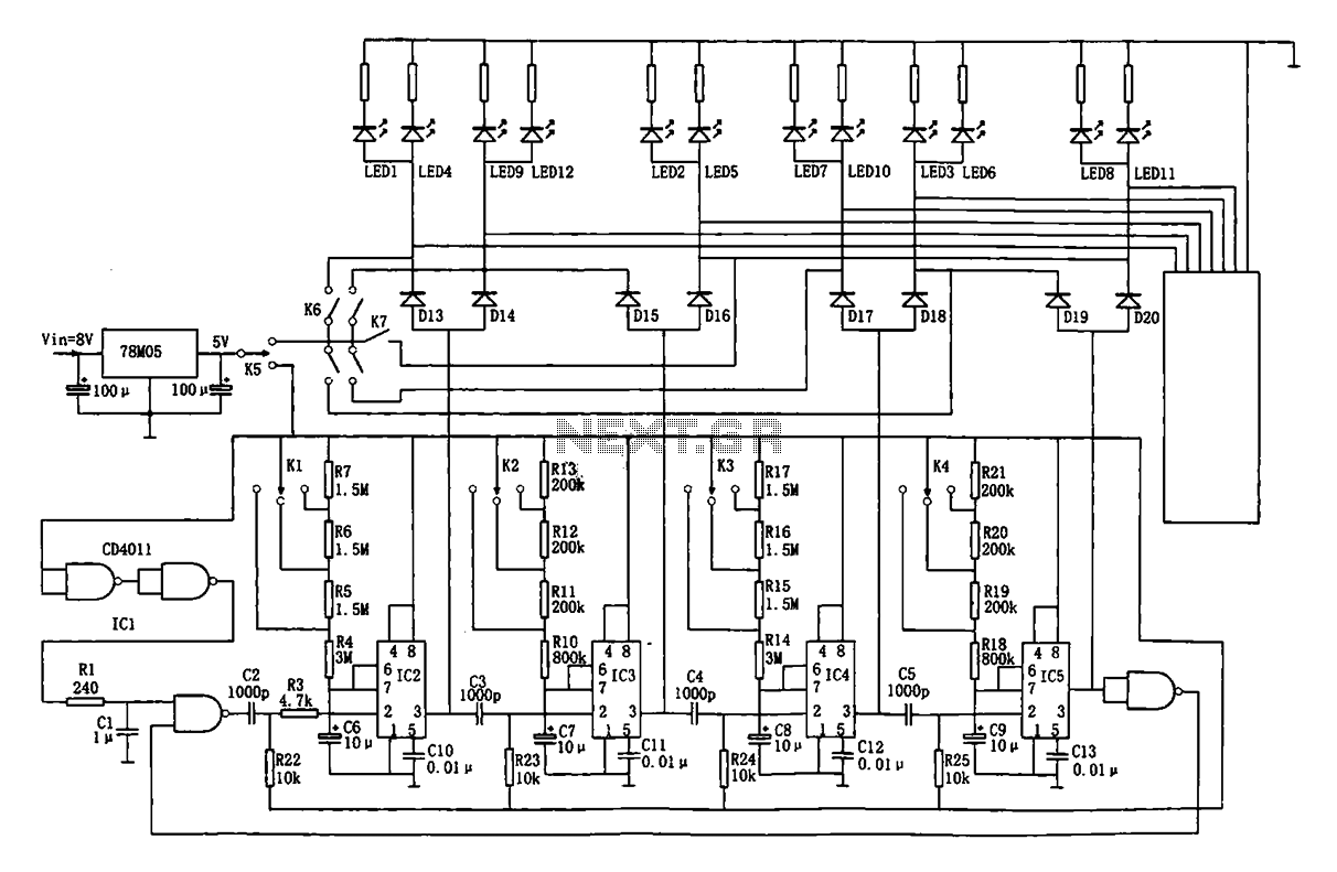
This document describes an automatic traffic intersection light control circuit. It features four monostable delay circuits, which consist of four 555 timer integrated circuits (IC2 to IC5) and several RC components interconnected. An 8V input voltage is regulated through...
The following diagram is for the main circuit of the motor driver. A testing version is shown near the end of this page. It is laid out differently and shows the SN7474 in logic block form and LEDs are...
This is a schematic diagram of a Permanent Magnet Motor Control circuit. This circuit is used to control the operation of a permanent magnet motor. The Permanent Magnet Motor Control circuit is designed to efficiently manage the performance of permanent...
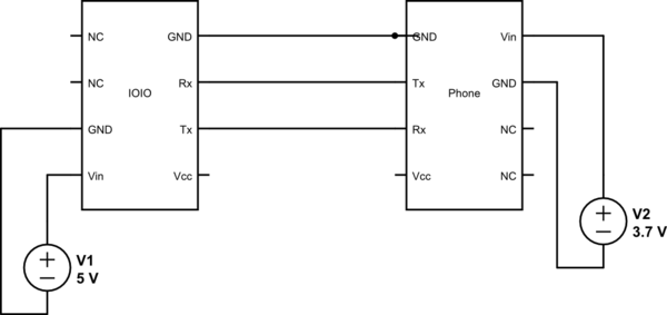
This project utilizes Sparkfun's IOIO for Android, focusing on power consumption concerns. The IOIO board can provide the phone with 500 mA charging, which may be excessive for continuous operation. The proposed solution is to power both the phone...