
QRP Antenna Tuner
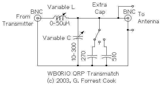
The described QRP antenna tuner, or transmatch, is designed to facilitate efficient power transfer from a low-power transmitter to a variety of antennas across the shortwave amateur radio bands, specifically from 3 MHz to 30 MHz. The primary function of this circuit is to match the impedance of the transmitter, which is conventionally 50 ohms, to the potentially mismatched impedance of the connected antenna. This impedance matching is crucial for optimizing signal transmission and minimizing signal loss due to reflections.
The core components of the circuit include a variable inductor and a variable capacitor. The variable inductor is placed in series with the transmission line, allowing for adjustment of the inductive reactance to match the antenna's impedance. The variable capacitor is connected to ground and is used to adjust the capacitive reactance. By tuning these two components, the user can achieve resonance at the desired frequency, which maximizes the power transfer to the antenna.
In practical implementation, the circuit is typically connected to a standing wave ratio (SWR) meter. The SWR meter provides real-time feedback on the impedance matching quality, indicating whether the circuit is tuned correctly. An SWR value of 1:1 indicates perfect matching, while higher values suggest a mismatch that could lead to power loss or damage to the transmitter.
The design of the circuit allows for versatility, accommodating a wide range of antenna types and configurations. This adaptability is particularly beneficial for amateur radio operators who may utilize various antennas for different bands and conditions. The construction of the tuner can be achieved using standard electronic components, making it accessible for hobbyists and engineers alike.
Overall, this QRP antenna tuner circuit exemplifies a fundamental tool in amateur radio, enhancing communication capabilities by ensuring efficient power delivery to antennas across a broad frequency spectrum.This circuit is for a QRP (low power) antenna tuner, a.k.a. a transmatch, for use in the short wave amateur radio bands from 3-30 Mhz. It allows a wide variety of antennas to be connected to a low power transmitter. When the circuit is properly tuned, the maximum transmitter power will be delivered to the antenna. It is used in conjunction with a standing wave ratio (SWR) meter. This is a fairly generic antenna tuner circuit. The purpose of a transmatch is to match the impedance of a transmitter, typically 50 ohms, to an unknown antenna impedance. The circuit consists of a variable series inductor followed by a variable capacitor to ground. Most transmitter outputs consist of 🔗 External reference
Related Circuits
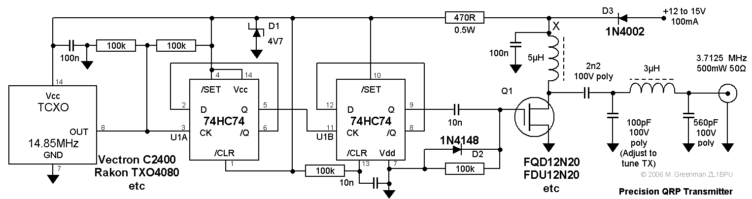
This compact transmitter is suitable for less demanding Doppler propagation measurements. It is designed for operation on the 80m band but can be easily adapted for the 40m or 20m bands. The output power is approximately 500mW of unmodulated...
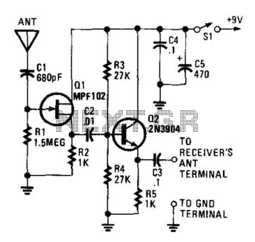
This circuit is designed to enable a short pull-up antenna to function similarly to a long wire antenna, without providing any voltage gain. The circuit enhances the receiver's performance only if the signal at the antenna is sufficiently strong...
This HD TV UHF wideband amplifier (Ultra High Frequency amplifier) provides a total gain of 10 to 15 dB within the frequency range of 400 to 850 MHz, making it suitable for areas with weak TV signals. To ensure...
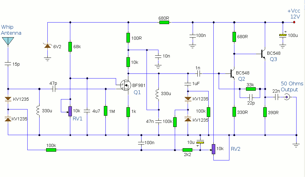
The antenna amplifier circuit comprises approximately 40 components, featuring two NPN transistors (BC548), one MOSFET (BF981), two varicap diodes (KV1235), and a 6.2V zener diode. It includes a 330µH inductor/coil, which can be modified for operation on different frequency...
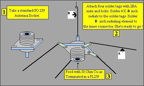
Two aluminum rods, each of length "L" in meters, are connected through an insulator as illustrated in the figure. A 75-ohm cable is fed from the center, similar to a conventional TV antenna. This configuration describes a basic antenna system...
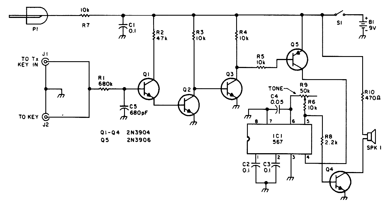
This circuit is designed for low-power transmitters that operate with a positive keying voltage. The transistors Q1, Q2, and Q3 are configured as a switching amplifier. When the key is pressed, the collector of Q3 connects to ground, which...