
quad power supply for hybrid amplifier
The power supply circuit is designed to provide multiple regulated voltage outputs suitable for various applications, particularly in audio amplification. The use of a cascade generator for the high voltage supply ensures that the required 170 V is achieved efficiently, which is critical for the proper functioning of the SRPP stage in the hybrid amplifier. The choice of components, including the LT1074CT voltage regulator and Schottky diodes, contributes to the overall efficiency and reliability of the power supply.
The inclusion of a heatsink for the regulators is essential for thermal management, particularly for the 12 V regulator, which must handle the load from the ECC83 valve filaments. The design considerations, such as the selection of transformer ratings and the arrangement of components on the heatsink, reflect a thorough approach to ensuring stable operation under varying load conditions.
Furthermore, the option to use an LT1074HVCT allows for flexibility in transformer selection, accommodating higher input voltages and enabling the generation of higher output voltages if desired. The overall layout and component choices are indicative of best practices in power supply design, aimed at achieving optimal performance while maintaining ease of assembly and reliability.
In summary, this power supply circuit is a well-thought-out design that meets the specific needs of the Simple hybrid amplifier while also allowing for broader applications, showcasing effective engineering principles in its construction.This power supply was designed for use with the Simple hybrid amp` published elsewhere in this issue. It is of course suitable for use in other applications as well. We`ve used a cascade generator for the 170 V, a switch mode supply for the 16 V, a series regulator for the 12 V and a separate transformer for the 6.
3 V filament supply. We`ve chosen an LT1074CT (IC1) for the regulator, which means that the circuit can be built with relatively standard components and will have a high efficiency. The power loss is less with this device compared to a linear voltage regulator. This allows us to use a higher transformer voltage and a smaller cascade section to generate the 170 V (which is required for the SRPP stage in the amplifier).
The lower input current also results in smaller losses in the bridge rectifier (D1 to D4). A standard 12 V regulator (IC2) turns the 16 V into a stabilised voltage for the buffer stage. When an ECC83 (12AX7) is used in the hybrid amp we could use this 12 V to power the filaments in the valve as well, although we really need 12. 6 V. The current taken by the valve is about 150 mA, which means that the 12 V regulator needs to be fitted with a heatsink.
This can be a small version of an SK129 heatsink from Fischer (38. 1 mm, 6. 5 K/W). To increase the voltage by 0. 6 V we`ve added diode D7 to the ground connection of the regulator. If an output voltage of 12 V is required you should close JP1, which shorts D7. IC1 and D5 require a little more cooling and for this the 63. 5 mm version of the SK129 will suffice (4. 5 K/W). Both components can be mounted on opposite sides of the heatsink. You have to make sure that they are electrically isolated from each other and the heatsink! You should take a look at the website of Linear Technology ( and take note of the layout recommendations regarding the use of an LT1074. You can use standard chokes for L1 and L2, rated at 5 A. If you want to remove more of the residual 100 kHz switching frequency you could always add an extra LC filter at the output.
The diodes in the bridge rectifier are B10100`s. These are Schottky rectifiers, which have a low forward voltage drop (only 0. 7 to 0. 8 V at 10 A). We have chosen diodes with a reverse voltage rating of 100 V so we have the option of using an LT1074HVCT instead. This can work with an input voltage of up to 60 V, which means we could use a 40 VAC transformer. The same cascade circuit can then easily generate 220 VDC. The standard LT1074CT can cope with up to 45 V, so we`re using IC1 fairly close to the limits of its specifications in this circuit.
A cascade circuit generates the HT supply for the valve. It would also have been possible to use a separate transformer with a bridge rectifier and smoothing capacitor to generate this voltage. But then we`d have to find a 4. 5 VA transformer with a 40 V secondary and connect it the wrong` way round. As this isn`t exactly a standard transformer we dropped that idea. The source for the cascade generator is now an 80 VA transformer. The capacitors in the cascade circuit have higher values than are strictly necessary. This makes it easier to calculate the expected output voltage. In our case this is 4 x 30 x v2V for the no-load voltage, which comes to nearly 170 V. L3 and C22 filter out any HF interference coming from IC1. When the cascade supplied 20 mA the output voltage dropped to 140 V. At heavier loads we recommend that you use a smaller cascade circuit and a higher transformer voltage (and also use an LT1074HVCT because of the higher input voltage).
The filament voltage for the valve is generated by a 4. 5 VA transformer, which in practice had an output a bit above 6 V and therefore came closer to the required 6. 3 V. Another solution is to use a special transformer or a stabilised 6. 3VDC supply. Any of these will work, so it`s down to your own preference which of these you`ll use. It is in principle possible 🔗 External reference
Related Circuits
This low power FM transmitter is designed to utilize an input from another sound source and transmits on the commercial FM band. The transmitter is relatively powerful for its category. The first stage consists of an oscillator, which is...
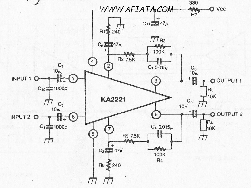
Audio amplifier circuit board with a dual low noise equalizer amplifier. The KA2221 is a monolithic integrated circuit that features 2-channel low noise amplifiers and a regulated power supply designed for car stereos. Key features include suitability for car...
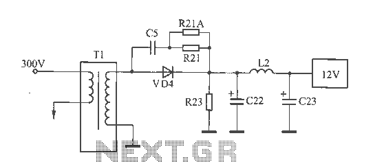
The 12V voltage instability should first be investigated by checking the output section of the switching power supply, as illustrated in the accompanying figure. The secondary winding of the transformer and the switch VD4 have been examined and found...
The circuit is designed to create a power amplifier that utilizes E80CC and EL34 vacuum tubes to achieve optimal performance, providing an output of 35 Watts. The power amplifier circuit employs E80CC and EL34 vacuum tubes, which are known for...
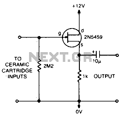
This circuit matches the very high impedance of ceramic cartridges, providing unity gain and low impedance output. By "loading" the cartridge with a 2.2MΩ input resistance, the cartridge characteristics are adjusted to closely compensate for the RIAA recording curve....
Nearly all modern computers are equipped with logic blocks that facilitate the implementation of a USB port. A USB port can deliver over 100 mA of continuous current at 5V to peripherals connected to the bus. Therefore, it serves...
Warning: include(partials/cookie-banner.php): Failed to open stream: Permission denied in /var/www/html/nextgr/view-circuit.php on line 713
Warning: include(): Failed opening 'partials/cookie-banner.php' for inclusion (include_path='.:/usr/share/php') in /var/www/html/nextgr/view-circuit.php on line 713