
Quad Power Supply For Hybrid Amplifier circuit
The power supply circuit integrates multiple voltage outputs tailored for specific operational requirements. The 170 V output is generated using a cascade generator, which provides a stable high voltage necessary for the functioning of the hybrid amplifier. This design choice enhances the overall performance by ensuring that the high voltage is generated efficiently, minimizing ripple and noise.
For the 16 V output, a switch-mode power supply (SMPS) is implemented. This type of supply is known for its efficiency and compact design, making it ideal for applications where space and thermal management are critical. The switch-mode topology allows for reduced power losses compared to traditional linear power supplies, which is particularly beneficial in minimizing heat generation.
The 12 V output is regulated using a series voltage regulator, specifically the LT1074CT. This component is advantageous due to its high efficiency, which is essential for maintaining a low thermal profile. It can handle significant load currents while providing a stable output voltage, making it suitable for powering sensitive electronics within the amplifier.
Lastly, the 6.3 V filament supply is derived from a separate transformer. This dedicated supply is crucial for powering the filaments of vacuum tubes or other components that require a specific filament voltage. Using a transformer ensures that this supply is isolated from the other voltage outputs, enhancing safety and reducing the risk of interference.
Overall, this power supply circuit exemplifies a well-thought-out design that prioritizes efficiency, reliability, and versatility. The choice of components and topologies ensures that it can meet the demands of the hybrid amplifier while remaining applicable to a range of other electronic applications.This power supply was designed for use with the ˜Simple hybrid amp published elsewhere in this issue. It is of course suitable for use in other applications as well. We ve used a cascade generator for the 170 V, a switch mode supply for the 16 V, a series regulator for the 12 V and a separate transformer for the 6.3 V filament supply.
We ve chosen an LT1074CT (IC1) for the regulator, which means that the circuit can be built with relatively standard components and will have a high efficiency. The power loss is less with this device compared to a linear voltage regulator.. 🔗 External reference
Related Circuits
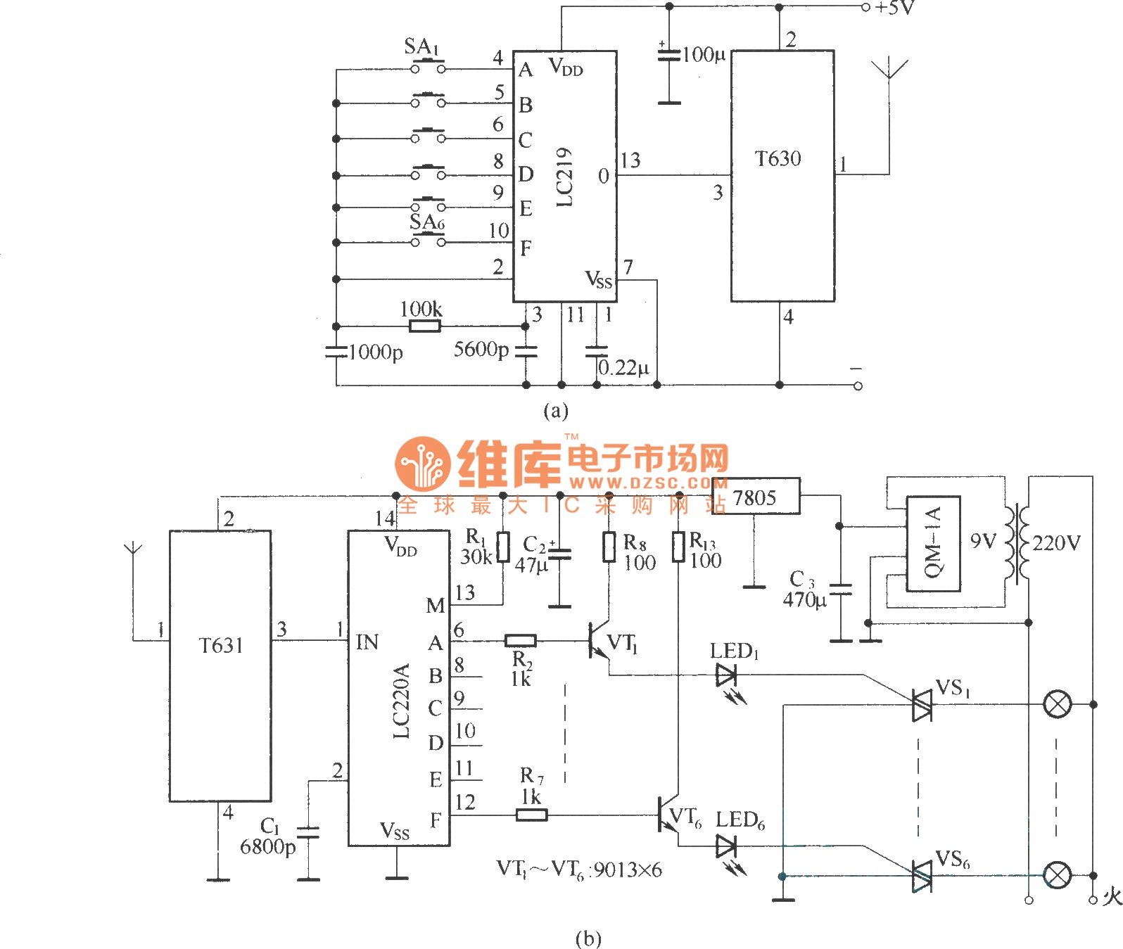
The circuit utilizes the long-wave wireless transceiver T630/T631 to manage a 6-channel load. It is characterized by low power consumption, high resistance to interference, and a simple structure. The circuit design incorporates the T630/T631 transceiver, which operates in the long-wave...
The circuit detects a sudden shadow falling on the light-sensor and sounds the bleeper when this happens. The circuit will not respond to gradual changes in brightness to avoid false alarms. The bleeper sounds for only a short time...
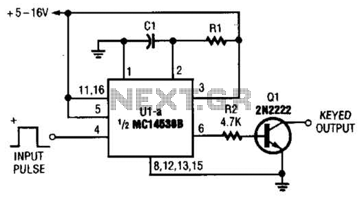
With switch SI in the off position, battery voltage is applied across timing capacitor CI, which remains charged while the rest of the circuitry is powered off. Transistor Q1, and consequently transistors Q2 through Q4, remain in an off...
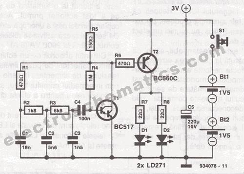
This infrared transmitter is designed for use with an infrared receiver. It operates using either two 1.5V batteries or a 3V lithium battery, allowing for a compact infrared communication system. The infrared transmitter circuit typically consists of an infrared LED,...
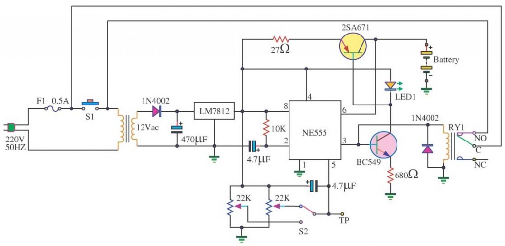
This innovative buzzer circuit incorporates a relay connected in series with a small audio transformer and a speaker. When the switch is activated, the relay is energized through the primary winding of the transformer and the closed relay contact....
In a lithium-ion cell, a voltage of 3.8V per cell indicates a state of charge of approximately 50%. It is important to note that using voltage as a fuel gauge is not precise, as cells manufactured by different companies...
Warning: include(partials/cookie-banner.php): Failed to open stream: Permission denied in /var/www/html/nextgr/view-circuit.php on line 713
Warning: include(): Failed opening 'partials/cookie-banner.php' for inclusion (include_path='.:/usr/share/php') in /var/www/html/nextgr/view-circuit.php on line 713