
Basic Infrared IR Transmitter Circuit
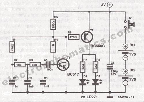
The infrared transmitter circuit typically consists of an infrared LED, a resistor, and a power source. The infrared LED emits light in the infrared spectrum, which is not visible to the human eye but can be detected by an infrared receiver. The choice of power source, either two 1.5V batteries in series or a single 3V lithium battery, provides flexibility in terms of size and capacity.
In the circuit, the infrared LED is connected in series with a current-limiting resistor to prevent excessive current flow that could damage the LED. The value of the resistor is determined based on the forward voltage and current specifications of the LED, as well as the voltage supplied by the batteries. For example, if the forward voltage of the infrared LED is 1.2V and the desired forward current is 20mA, the resistor value can be calculated using Ohm's law.
The transmitter may also include a modulation circuit to encode data onto the infrared signal, allowing for more robust communication. This can be achieved using a simple microcontroller or a timer IC that generates a square wave signal, which modulates the infrared LED's emission. The modulation frequency should be chosen based on the specifications of the corresponding infrared receiver to ensure optimal performance.
Overall, the infrared transmitter circuit is a vital component in remote control systems, wireless data transmission, and various applications requiring short-range communication. Its simplicity and effectiveness make it a popular choice for hobbyists and professionals alike.This infrared tranmitter is intended for use with this infrared receiver. It works with 2 - 1.5V batteries or a 3V lithium battery. To give a compact infra.. 🔗 External reference
Related Circuits

Spring reverb produces a clean and natural sound, often perceived as exceptionally good for a spring reverb. However, when the reverb springs are struck forcefully, they create explosive dub-like effects. Spring reverb is an analog sound processing technique that utilizes...
The W7800 is a positive integrated voltage regulator, while the F007 consists of an operational amplifier used in a power supply tracking application circuit. Some configurations utilize both positive and negative power supplies, with a negative supply necessary to...
Here is a circuit diagram for adjusting the brightness of a light bulb. The second battery is utilized to power the circuit. This circuit can be used to modify the brightness of images during close-up photography with a digital...
Described timer to participate in the current circuit switch - bulb without any modification of existing pipelines. Connect the timer is in Figure 1 The time switch has only two outlets, which is connected in parallel to the button...

When the tank is empty, the wires within it are open-circuited, causing the 180K resistor to pull the switch low, resulting in the switch being open and the LEDs being OFF. As water begins to fill the tank, the...

A simple and cost-effective water level indicator circuit can be designed using this schematic. This water level indicator utilizes a CMOS IC CD4066 to indicate the amount of water present in an overhead tank and to provide an alarm...