
Questions about colpitts oscillator design
For a better understanding of the operation of LC tank oscillators, reference to visual aids, such as animations of Colpitts and Clapp oscillators available on platforms like YouTube, is recommended. There are some concerns regarding the use of symbols without sufficient explanation, particularly regarding the dynamic input resistance of the amplifier stage, denoted as "RB," and the total emitter resistance, represented as "RE(total) = RE + re," which serves as an intermediate calculation for the total resistance.
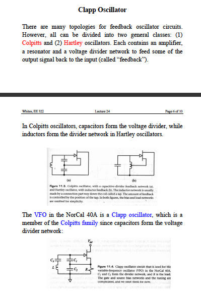
The original circuit design can also accommodate the Clapp oscillator configuration by reducing the value of C0, thus forming a series LC resonator. However, it was established from the outset that C0 is sufficiently large to function solely as a DC blocking capacitor. The functional differences between series resonant Clapp and parallel resonant Colpitts circuits are significant enough to warrant separate discussions. The analysis of the Colpitts circuit is already complex, and while the original circuit can also serve as a Clapp oscillator, the conditions for its operation must be clearly defined.
It is important to note that the circuit requires an initial charge before oscillations can commence. Given that this capacitor has a large capacitance value, the charging process can take a considerable amount of time, potentially leading to stagnation in oscillation initiation. The oscillator's reliability and functionality are discussed in literature concerning the NorCal radio transceiver, a well-regarded unit. Subsequent calculations include a formula for resonant frequency that accounts for all three capacitors, indicating that the capacitor adjacent to the inductor is sufficiently small to influence the overall circuit behavior alongside the other capacitors.
The common collector (CC) circuit, often referred to as an emitter follower, is characterized by its low output impedance and high input impedance, making it suitable for impedance matching applications. However, the mutual dependence of input and output impedances complicates the design process. In contrast, the common base (CB) configuration presents a more stable impedance relationship, allowing for better isolation between the input and output stages of the amplifier.
In the context of oscillator design, particularly with LC tank circuits, the selection of capacitors and inductors is critical. The choice of C0 not only affects the DC blocking characteristics but also influences the resonant frequency and stability of the oscillation. The analysis of the Colpitts oscillator, which typically employs a parallel capacitor configuration, highlights the necessity of understanding the role of each component in achieving desired performance metrics.
The mathematical treatment of these configurations often involves complex calculations that take into account frequency response, phase shift, and feedback mechanisms. The interaction between reactive components can lead to variations in oscillation frequency, necessitating careful tuning and design considerations to ensure reliable operation.
In summary, while impedance matching in CC circuits may not yield optimal results due to the interdependence of parameters, alternative configurations such as CB can enhance performance. Understanding the nuances of oscillator design, including the implications of component selection and circuit topology, is essential for achieving reliable and effective electronic systems.amplifier input and output impedance, load and source resistance are strongly mutually dependent in the CC circuit. That`s a reason, why "impedance matching" doesn`t achieve results representative for the circuit operation.
Analyzing the circuit as CB with virtual ground, as suggested by LvW, gives a better decoupling of both amplifier ports. Impe dance matching isn`t a bad design idea, when the amplifier power gain is small and must be well utilized to get the oscillator working at all. But it must consider the actual frequency dependent transistor parameters. - amplifier input and output impedance, load and source resistance are strongly mutually dependent in the CC circuit.
That`s a reason, why "impedance matching" doesn`t achieve results representative for the circuit operation. Analyzing the circuit as CB with virtual ground, as suggested by LvW, gives a better decoupling of both amplifier ports.
Impedance matching isn`t a bad design idea, when the amplifier power gain is small and must be well utilized to get the oscillator working at all. But it must consider the actual frequency dependent transistor parameters. For an aid to understanding the operation of these LC tank oscillators, I suggest you watch my Youtube videos which show an animation of Colpitts and Clapp oscillators.
It`s a pity that samy uses symbols without sufficient explanation, but I think he didn`t make any error as far as RE is concerned (but I am surprised about his comment "yes, you are right"). According to his calculation I suppose the symbol "RB" stands for the resulting DYNAMIC input resistance of the whole amplifier stage and the symbol "RE(total)=RE+re" is just an intermediate step for the sum of two resistances.
It`s true, that the original circuit also covers the clapp oscillator option by making C0 small and constituating a series LC resonantor. But it has been clarified from the start that C0 is sufficient large to act as a DC block only. Functionally, series resonant clapp and parallel resonant colpitts circuit are sufficiently different to distinguish them in the discussion.
The exact analysis of the colpitts circuit is already demanding enough. It`s true, that the original circuit also covers the clapp oscillator option by making C0 small and constituating a series LC resonantor. But it has been clarified from the start that C0 is sufficient large to act as a DC block only. Functionally, series resonant clapp and parallel resonant colpitts circuit are sufficiently different to distinguish them in the discussion.
The exact analysis of the colpitts circuit is already demanding enough. However it must charge up initially before oscillations get underway. Since it is a large uF value, this takes substantial time. The circuit can easily stagnate. It is not guaranteed to start oscillating. I am acquainted with this oscillator. It is discussed in articles about the NorCal radio transceiver. (A well-designed unit which became popular due to its reliability and functionality. ) Subsequent pages show math calculations. I see a formula for resonant frequency. It includes all three capacitors. This implies the one next to the inductor is small enough to have an influence along with the other capacitors. 🔗 External reference
Related Circuits
A field effect transistor amplifier features a fixed bias input source with feedback, resulting in very high input impedance and low capacitance. It drives a field effect transistor or emitter follower, despite having a very low output impedance, utilizing...
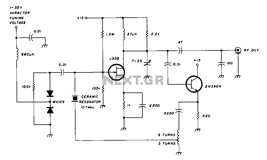
The design involves using a 555 timer as an oscillator in the high voltage power supply section. There is a query regarding the possibility of altering the design to utilize an output from a microcontroller to generate an oscillating...
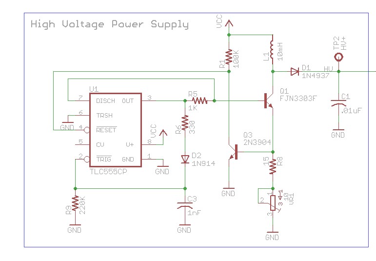
This article discusses the design of an LED driver for automotive rear lights. It demonstrates that dimming is most effectively accomplished using pulse-width modulation (PWM) in conjunction with an LED driver integrated circuit (IC) that removes the requirement for...
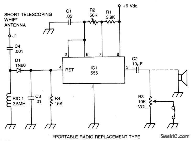
A sidetone oscillator is a specialized audio oscillator that is activated and deactivated in conjunction with the transmitter. This oscillator is driven by RF signals and is powered by batteries. It employs a 555 integrated circuit (IC) timer configured...
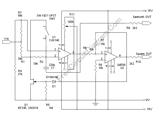
This voltage-controlled oscillator circuit is compact and exhibits good linearity. The precision can be better than 0.01% if properly constructed. The circuit provides three different output waveforms: square, triangle, and sawtooth, which are essential for music synthesizers and measurement...

This document outlines the design process of a control circuit for a stepper motor. Given the characteristics of the stepper motor, the control circuit was developed as a state machine that transitions through four output states depending on two...