
RE POWERED SIDETONE OSCILLATOR
The sidetone oscillator plays a crucial role in communication systems, particularly in radio transmission. It provides an audio feedback signal that allows the operator to monitor the transmitted signal. The 555 timer, functioning as an astable multivibrator, produces a continuous square wave output, which can be adjusted in frequency by varying the external resistors and capacitors connected to it.
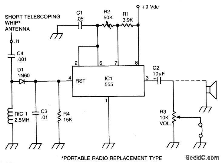
In this configuration, the RF-driven aspect of the oscillator ensures that it operates in sync with the transmitter's signal. When the transmitter is keyed, the RF signal generates a positive DC potential that resets the 555 timer, effectively turning the oscillator on. This results in an audible tone that corresponds to the transmission, allowing the operator to hear the sidetone while transmitting.
The circuit typically includes a few passive components such as resistors and capacitors, which determine the frequency and duty cycle of the output waveform. Additionally, a speaker or audio output device is connected to the output of the 555 timer to convert the electrical signal into sound. The battery operation makes the sidetone oscillator portable and suitable for various applications in field communication setups.
Overall, the sidetone oscillator enhances the usability of radio transmitters by providing essential audio feedback, contributing to effective communication practices.A sidetone oscillator is a special audio oscillator that is turned on and off with the transmitter. The oscillator is rf-driven and bat-tery operated. It uses a 555 IC timer as an astable multivibrator. Keying is accomplished by applying a positive dc potential, developed from the rf signal, to the reset terminal of the 555. 🔗 External reference
Related Circuits
Introduction The MIC2290 is an internally compensated standard step-up switching regulator that features an integrated power switch and Schottky diode. The inclusion of these components makes the MIC2290 an optimal solution for 48V Avalanche Photo Diode (APD) applications. In...
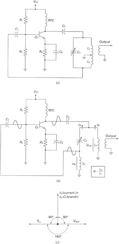
A widely recognized circuit is the Hartley oscillator, which is characterized by a tapped coil within the LC tank circuit. The tap point of the coil is grounded. The oscillator's amplifier section functions as a common-emitter amplifier, resulting in...
A phase-locked loop (PLL) is widely utilized in telecommunications, control systems, and various other electronic applications. PLLs can be employed to demodulate frequency-modulated (FM) signals and generate a stable output frequency. A phase-locked loop is an essential feedback control system...

This design schematic illustrates a Crystal Colpitts oscillator that can be implemented using a transistor and a parallel mode crystal. In this circuit, the crystal functions as an inductance. A large value capacitive divider is utilized between the gate,...
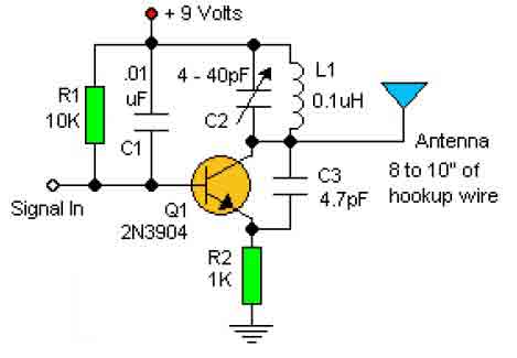
This basic RF oscillator circuit is easy to build and the components are not critical. Most of them can be found in your junk parts box. The L1 antenna coil can be made by close winding 8 to 10...
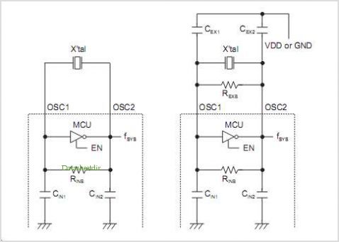
The hysteresis characteristic indicates that the voltage level transitions to high (H) when the input voltage of the inverter rises from 0 V, and the voltage level transitions to low (L) when the input voltage descends from +5 V....