
Honey Bee Counter Circuit
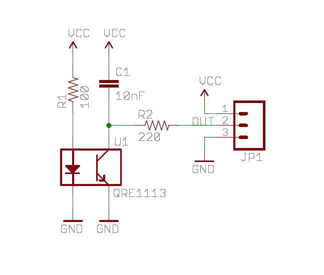
The described circuit operates on a dual-sensor system that detects the movement of bees through a designated gate. The real-time clock is programmed to deactivate the counting function during nighttime hours, thereby minimizing power consumption. The core of the system involves an LED that illuminates the pathway, and a phototransistor that detects the reflected light. This reflection indicates the presence of a bee passing beneath the LED.
The alignment of two sensors allows for directional detection of the bees. When a bee approaches the gate, it will first interact with one of the sensors. If the inside sensor is triggered first, it indicates that the bee is exiting the area; conversely, if the outside sensor is activated first, it indicates that the bee is entering. This functionality is crucial for monitoring bee activity and can be used for various research or agricultural applications.
The sensitivity of the phototransistor is adjustable through the use of resistors connected to ground. The choice of a 100k ohm resistor is significant as it optimizes the sensitivity of the circuit, allowing for reliable detection of the bees. If a resistor with a lower resistance value were used, the circuit would become less sensitive, potentially leading to missed detections. The NPN phototransistor serves as the light sensor, converting the incident light into an electrical signal that can be processed by the Arduino or Teensy microcontroller.
In summary, this circuit effectively combines a real-time clock, phototransistor sensors, and a microcontroller to create a responsive and energy-efficient monitoring system for bee movement. The design considerations regarding sensitivity and sensor placement are critical for the accurate functioning of the system.Real time clock turns OFF the counter at night for reduced power. When the bee crosses under the LED the light is reflected back to the sensor. (its a photo transistor) and triggers a digital input to the Arduino. (or teensy in my case). I lined up two chips right ne xt to each other. as the bee goes through the gate if it hits the inside sensor first. its going out. if it hits the outside sensor first its coming in. More on the programming. - per the large schematic below, I used 100k ohm resistors to ground. this increases the sensitivity. If you use a smaller resistor it becomes less sensitive. It is an NPN Phototransistor. 🔗 External reference
Related Circuits

The wideband sinusoidal voltage-controlled oscillator circuit is designed such that the oscillation frequency is determined by an integrating resistor R and a capacitor C. The voltage-controlled oscillator is constituted by the applied control voltage Vc and a control resistor...

When the light beam that falls on the CDS photocell is interrupted, the transistor (EN3904) conducts, triggering SCR1 (CI06) and activating the alarm bell. SI resets the SCR. The alarm bell should be a self-interrupting electromechanical type. The lamp...

877 ~ 924MHz RF2152 power amplifier circuit diagram. The RF2152 is a high-performance power amplifier designed for applications in the 877 to 924 MHz frequency range. This amplifier is typically used in various RF communication systems, including wireless networks and...

This article discusses a home security alarm circuit designed to detect LPG gas leakage. The circuit utilizes a gas sensor module, SEN 1327, which incorporates a QM 6 gas sensor. The output signal from this gas sensor module is...

This design circuit outlines a simple, low-cost, and ultra-compact VHF/UHF Low-Noise Amplifier (LNA) that can be implemented using the MAX2664 and MAX2665 devices, which are specifically tailored for VHF/UHF applications. The MAX2664 operates within the UHF frequency range of...

This scheme is designed for a four-cylinder engine. It aims to reduce fuel consumption, increase speed slightly, and minimize the need for frequent access to the distributor cap for contact button replacement, thereby saving costs. Transistors T1 and T2...