
Winding electronic counter 2
The winding machine's electronic counter is designed to accurately measure and display the number of turns made during the winding process. The power circuit supplies the necessary voltage and current to the entire system, ensuring stable operation. The infrared switch circuit serves as a sensor to detect the position of the coil, triggering the counting mechanism each time a complete turn is made.
The shaping/transformation circuit processes the signals received from the infrared switch, converting them into a suitable format for counting. This circuit may include components such as operational amplifiers or Schmitt triggers to ensure clean and reliable signal transitions. The reset circuit allows the user to set the counter back to zero, providing flexibility for multiple winding operations without manual intervention.
The divider circuit is crucial as it can scale down the input signals to the appropriate level for the LED counter. This ensures that the counter can accurately reflect the number of turns, especially in applications where the coil may be wound rapidly. Finally, the LED counter visually presents the data, allowing operators to monitor the winding process in real-time.
Overall, the design of the winding machine electronic counter integrates multiple circuits to achieve precise measurement and user-friendly operation, making it an essential component in automated winding applications.The winding machine electronic counter described in the example uses LED digital display to show the wound coil turns, the use of maximum count rate is 9900 turns. The working principle The winding machine circuit is composed of the power circuit, infrared switch circuit, shaping / transformation circuit, reset circuit, divider circuit and the LED counter..
🔗 External reference
Related Circuits
Digital visitor counter is a reliable circuit that takes over the task of counting Number of Persons/ Visitors in the Room very Accurately. When somebody enters into the Room then the Counter is Incremented by one and when any...
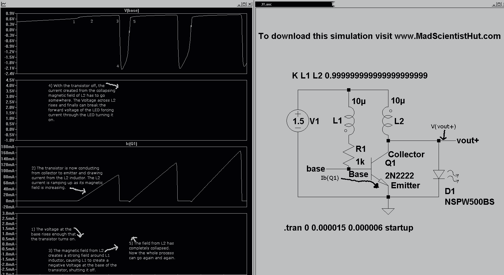
Introducing the Cree 1 Watt LED High Power Joule Thief Kit. Joule Thief Simulation II Graph and Schematic. The Cree 1 Watt LED High Power Joule Thief Kit is designed to demonstrate the principles of energy harvesting and efficient power...
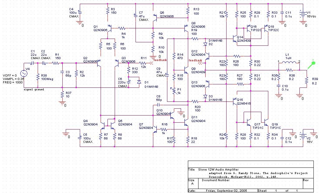
The project involves developing a 12W power amplifier circuit into a fully assembled hard-wired unit. This will require a design cycle and development sequence that includes analysis, simulation, printed circuit board (PCB) layout, board population, hard soldering, and testing....
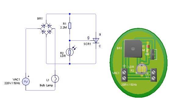
Adjust the value of R1 to achieve optimal performance of the LDR sensor. If, in practice, a resistance of 2.2 MΩ still activates the lamp, it is possible to increase the value of R1 to a larger resistance of...
The circuit consists of two twin-T oscillators configured to operate just below the oscillation threshold. To initiate oscillation, the circuit can be activated by touching the Touch Pad. The circuit utilizes twin-T oscillator configurations, which are known for their ability...
This circuit measures the distance covered during a walk. The hardware is housed in a small box that can be slipped into a pants pocket, with the display designed as follows: the leftmost display D2 (the most significant digit)...