
R/C-Plane altitude recorder
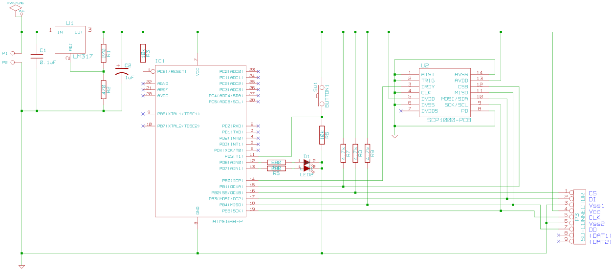
The circuit design incorporates several key components and considerations for optimal performance. The ATmega8 microcontroller serves as the central processing unit, managing data acquisition from the SCP1000 and interfacing with the SD card for data storage. The SCP1000 sensor, which is crucial for measuring atmospheric pressure, operates through SPI communication, allowing for efficient data transfer. The LM317 voltage regulator ensures that the circuit operates within the required voltage range, safeguarding the components from potential damage due to overvoltage.
The integration of pull-up resistors on the SPI bus lines is essential for maintaining signal integrity and ensuring reliable communication between the microcontroller, SCP1000, and SD card. The use of status LEDs provides visual feedback to the user, indicating the operational status of the circuit and any potential errors that may arise during operation.
The decision to employ a PCB instead of a stripboard reflects a commitment to compactness and reliability, particularly given the constraints of fitting the circuit into an R/C glider. The modular design, allowing for the SCP1000 to be connected via multipoint connectors, facilitates easy replacement and maintenance of the sensor without the need for soldering.
Overall, this R/C plane altitude recording circuit exemplifies a practical application of microcontroller technology and sensor integration, providing hobbyists with a valuable tool for enhancing their flying experience through altitude data collection. The approach taken in the design and implementation of this circuit demonstrates a clear understanding of both hardware and software requirements necessary for successful operation in a remote-controlled environment.This is a circuit to record the altitude of a R/C-plane. The data is saved on a SD-Card. It uses an ATmega8 microcontroller and a SCP1000 chip to measure temperature and (more important) atmospheric pressure. If you decide to build and use this circuit, you do so at your own risk. This is just a hobby project, so I don`t take liability for any dam age or harm it might cause. The circuit is powered by battery or the R/C receiver (5V). The LM317 regulates the voltage to 3. 3V, which is the operational voltage of SD-Cards and just high enough for the ATmega8. The atmospheric pressure is measured by the SCP1000-D01 from VTI, which has an SPI interface. The single chip is available only in a SMD version, which cannot be handled manually. Luckily, it can also be bought premounted on a PCB carrier. The SD-Card shares the SPI bus with the SCP1000. The bus lines are held up by pull-up resistors. In addition to the ICs there are two status LEDs and a button to start and stop the recording of data. At first I wanted to build the circuit on a stripboard, but because of the many connecting lines the board would have been far too large to fit into my R/C-glider.
So a PCB was necessary, which I desinged with KiCad and then ordered from a manufacturer. Because the SCP1000 in the PCB version is quite expensive, it is not soldered to the PCB, but plugged in two rows of multipoint connectors. The the main tasks of the microcontroller software is to request and receive the temperature and pressure data from the SCP1000 and store the data on the SD-Card.
I was a little lazy here and did not implement a file system. After the initialization of the sensor and the SD-Card, the microcontroller searches for a certain byte-mark on the card. It writes recorded data in raw bytes onto the card beginning from the marked position. When recording stops it writes the mark in the first position of the next free block. During initialization only status LED 2 (red) lights up and starts flashing if an error occurs. When initialization is completed successfully, LED 2 goes out and LED 1 (green) turns on. The user can then start recording by pushing the single button. During recording LED 2 flashes while LED 1 is on. When the button is pressed again, recording stops. If an error occurs both LEDs start flashing. Before using the SD-Card, I made sure it is completely empty and freshly formatted in FAT16. After that I created a single text file containing the mark and trailing spaces, which fill all the availably memory on the card.
This way the recorded data is stored in the file, even though the microcontroller doesn`t know a thing about FAT. In every dataset atmospheric pressure and temperature are stored separated by commas. The datasets are separated by the newline character. The recorded data can be copied directly from the file into a spreadsheet. After that the altitude can be calculated with the barometric formula. Near ground level the atmospheric pressure decreases roughly 1 hPa every 8 meters. 🔗 External reference
Related Circuits
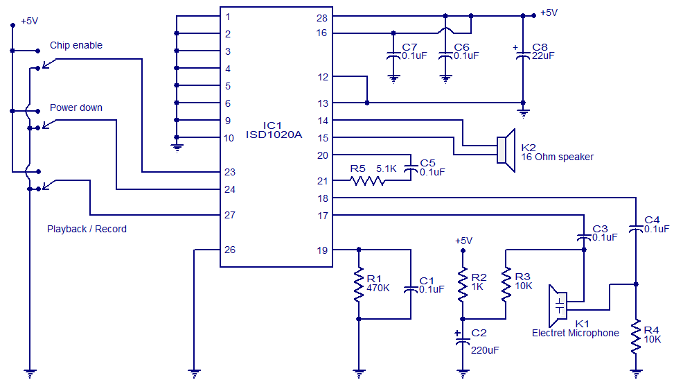
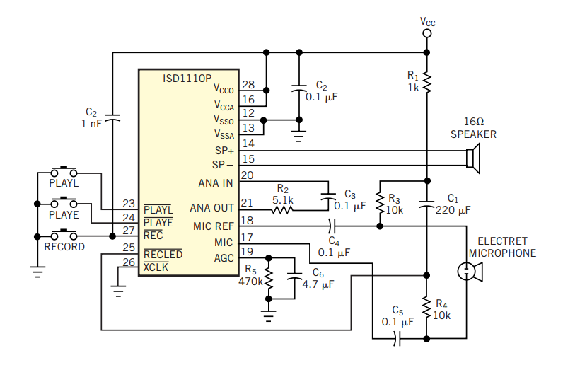
This circuit is designed in response to a request made by Mr. Vignesh for a voice recording and playback system. The circuit utilizes the ISD1020A IC from ISD, which is a CMOS single-chip record/playback device capable of recording voice...
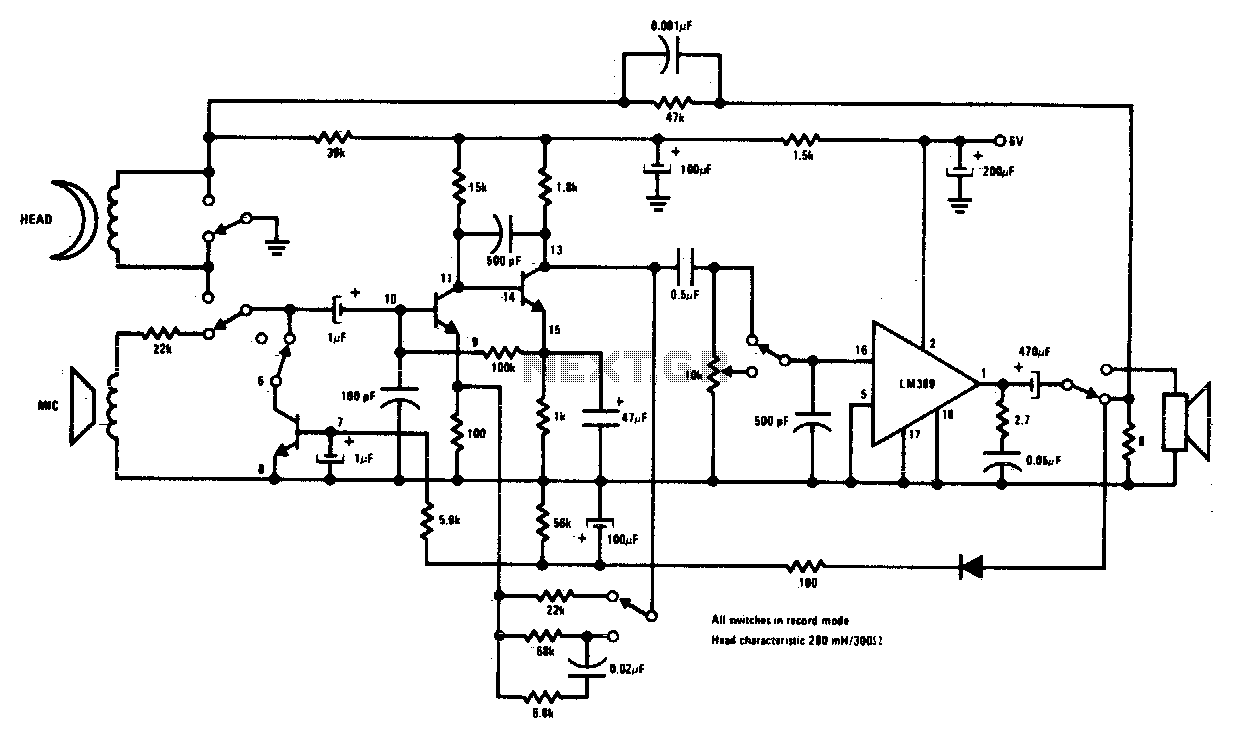
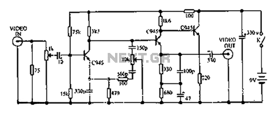
Complete record/playback cassette tape machine amplifier. Two of the transistors act as signal amplifiers, with the third used for automatic level control during the record mode. The cassette tape machine amplifier is designed to facilitate both recording and playback functionalities,...
The Z86E02 is one of ZiLOG's most popular Z8 One Time Programmables (OTPs). It features a 512-byte EPROM, 61 bytes of RAM, 14 I/O ports, a Watch-Dog Timer, Power-On Reset, a Low-Voltage Protection circuit, and an additional Timer. Notable...
The original input data describes a common situation in many companies where a single type of telephone is purchased for all employees. This is often done to take advantage of quantity discounts. However, this can lead to problems as the...
This circuit compensates for additional defects in image quality associated with LP (long play) recorders. The frequency components of the television signal reflect the details displayed on the screen. Enhancing the high-frequency components increases the edge sharpness of the...
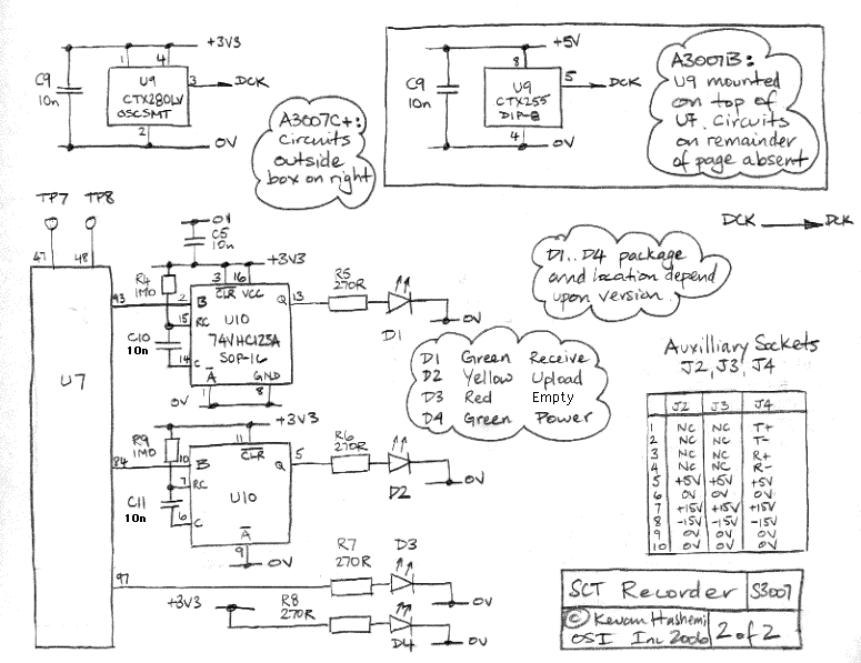
The Data Recorder (A3007) is a LWDAQ device that decodes and records subcutaneous transmitter (SCT) messages. The A3007 processes the signal generated by a demodulator, such as the Demodulating Amplifier (A3017), to identify valid SCT message sequences. It stores...