
LM4911 different power circuit conduction time recommended
The LM4911 is a power amplifier designed for audio applications, providing high efficiency and low distortion. The circuit configuration allows for various power conduction times, which can be critical in applications requiring precise control over amplifier performance to optimize power consumption and thermal management.
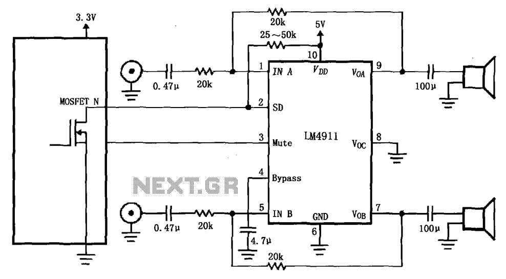
In this circuit, the MOSFET serves as a switch that is controlled by the shutdown (SD) terminal of the LM4911. When the SD terminal is activated, it turns on the MOSFET, allowing current to flow through the amplifier. The duration for which the MOSFET remains on is regulated by the controller, ensuring that the amplifier operates within its specified parameters for optimal performance.
The on-time regulation is essential for applications where battery life is a concern, as it prevents the amplifier from drawing excessive current when not in use. This feature is particularly useful in portable audio devices, where power efficiency directly impacts battery longevity.
Additionally, the design may incorporate feedback mechanisms to monitor the output and adjust the on-time accordingly, further enhancing the amplifier's efficiency and performance. Proper layout and component selection are also critical in minimizing noise and ensuring stable operation across varying conditions.
Overall, the implementation of the LM4911 with a controlled MOSFET shutdown feature presents a robust solution for managing power in audio amplification applications. As shown for the LM4911 different power conduction time recommended circuit. This circuit uses a controller, use the controller of the MOSFET LM4911 shutdown control (SD) termi nal is controlled to achieve on-time regulation of the amplifier.
Related Circuits
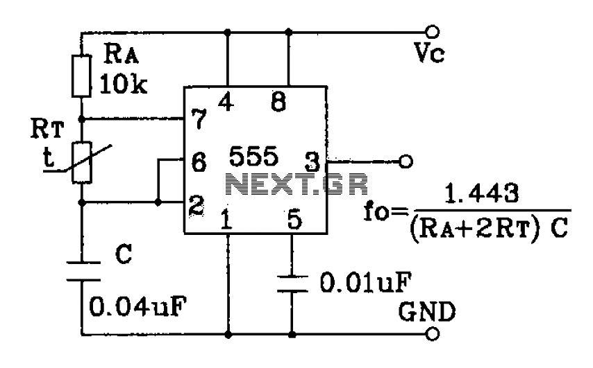
555 precision temperature sensor with temperature frequency converting circuit diagram consisting of: The 555 precision temperature sensor operates by converting temperature variations into frequency signals. This circuit typically utilizes a 555 timer IC configured in astable mode to generate...
AC level meters, such as VU meters, and DC level meters, such as signal meters, are used for measuring electrical signal levels. These devices feature a display consisting of nine red or green LEDs that represent the input level...

This design circuit for audio amplifiers with DC coupling to the load is not commonly used today, despite its clear advantages. One advantage is the elimination of the need for a second (symmetric) power supply, and another is the...
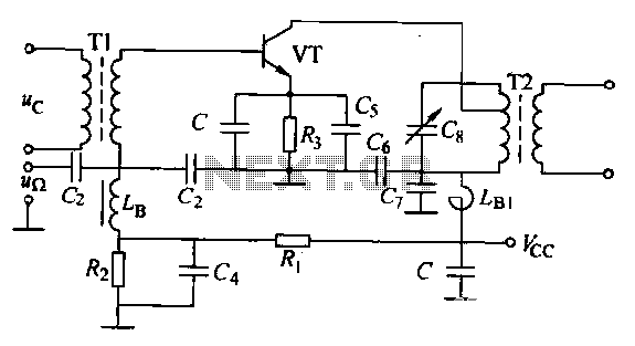
The circuit is designed for small-signal amplitude modulation (AM). Component C functions as a high-frequency bypass capacitor. Transformers T1 and T2 serve as high-frequency transformers, while the LC resonant circuit operates at the carrier frequency with a passband of...
This 555 timer circuit toggles a relay when a button is pressed. Pins 2 and 6, the threshold and trigger inputs, are held at half the supply voltage by two 10K resistors. When the output is high, the capacitor...
This circuit functions with inaudible (ultrasonic) sound. Sound of frequency up to 20 kHz is audible to human beings. The sound of frequency above 20 kHz is called ultrasonic sound. The circuit described generates (transmits) ultrasonic sound of frequency...