
radio controlled electronic flash
The radio-controlled electronic flash circuit integrates several key components to ensure reliable operation. The R/C car serves as the primary control mechanism, utilizing its built-in electronics to facilitate remote operation. The motor leads, which are modified to connect with an SCR, allow for control over the flash operation. The SCR (Silicon Controlled Rectifier) is crucial as it acts as a switch that can handle the high current required to trigger the flash unit.
To elaborate on the connection process, when the remote button is activated, it sends a signal to the transmitter, which in turn alters the polarity of the motor leads. This change is detected by the SCR, which is configured to switch on when the gate receives a positive signal. The flash extension cord, which connects the SCR to the electronic flash, must be carefully managed to ensure that it can handle the necessary voltage and current without degradation.
The arrangement of the components can vary based on the available space and aesthetic preferences. Utilizing a jiffy box not only protects the electronic components but also provides a professional appearance, making it suitable for use in various photography settings. The integration of Veroboard for additional circuit components enables a compact and efficient layout, ensuring that the system remains lightweight and portable.
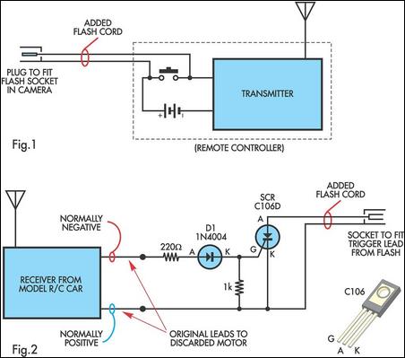
Overall, this circuit design exemplifies a practical application of radio control technology in photography, enhancing the capabilities of photographers by allowing them to control flash lighting without the constraints of wires. The reliability and simplicity of the system make it an attractive option for both amateur and professional photographers seeking to improve their lighting techniques.A radio controlled electronic flash is a useful item in any photographers kit. Professionals use them all the time. For example, a wedding photographer would put one behind the bride to back-light her gown and veil. You dont want wires showing in a shot like that. To build this control you will need an old R/C car (the simplest sort) in which the car runs in reverse at switch-on and goes ahead only when the remote is operated. They can be picked up cheaply as school fetes and garage sales. A typical car will run from 3V (two cells) and use 9V in the transmitter. Before proceeding, make sure that the electronics in the car are operating. It doesnt matter if the wheels are broken or the motor is dead. You need to gain access to the leads to the motor. Normally (ie, without the remote operating), one is positive with respect to the other. Label them accordingly. On pressing the remote button, the polarity of the motor leads should swap. You will also need a flash extension cord you can cut into two sections. At the transmitter, the camera end of the extension cord is fed into the case and soldered to the control button contacts, as shown in Fig. 1. The contacts are in series with the battery supply, so if you dont want to open the transmitter, just cut one of the battery leads and connect the flash extension cord into the gap so created.
You will then need to tape down the remote button so that it is permanently operated (ie, closed). All that needs to be done at the receiver end is to connect the normally negative motor lead to the gate circuit of an SCR, as shown in Fig. 2, while the normally positive lead goes to the cathode of the SCR. Now, when the transmitter is operated by the cameras contacts, the lead polarity is reversed and the SCR acts as a switch to fire a portable electronic flash via the other half of the flash extension cord.
The transmitter can be attached to the camera via a flash bracket or a screw into the tripod socket, depending on what is the most convenient arrangement. The added components in the receiver can be mounted on Veroboard and housed in the space where the electric motor was.
If appearance is a primary consideration, the receiver and the added components could be mounted in a standard jiffy box. 🔗 External reference
Related Circuits
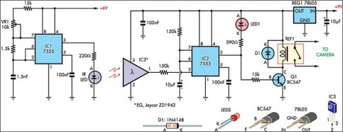
The IR detector (IC3) controls an LM 7555 CMOS timer (IC2) operating in monostable mode. When the beam is interrupted, IC2 is triggered, and its pin 3 output goes high for approximately half a second. This action extinguishes LED1...

One reason commercial soldering stations are costly is that they typically use soldering irons equipped with built-in temperature sensors, like thermocouples. This circuit design eliminates the necessity for a specialized sensor by directly sensing the temperature of a soldering...

This remarkably straightforward circuit enables the operation of one or two robust 12V 21W car bulbs in a flashing mode using a power MOSFET. Such devices are especially suitable for road, traffic, and yard alerts, as well as in...
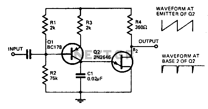
With the component values shown, the oscillator has a frequency of 8 kHz. When an input signal is applied to the base of Q1, the current flowing through Q1 is varied, thus affecting the time required to charge C1....
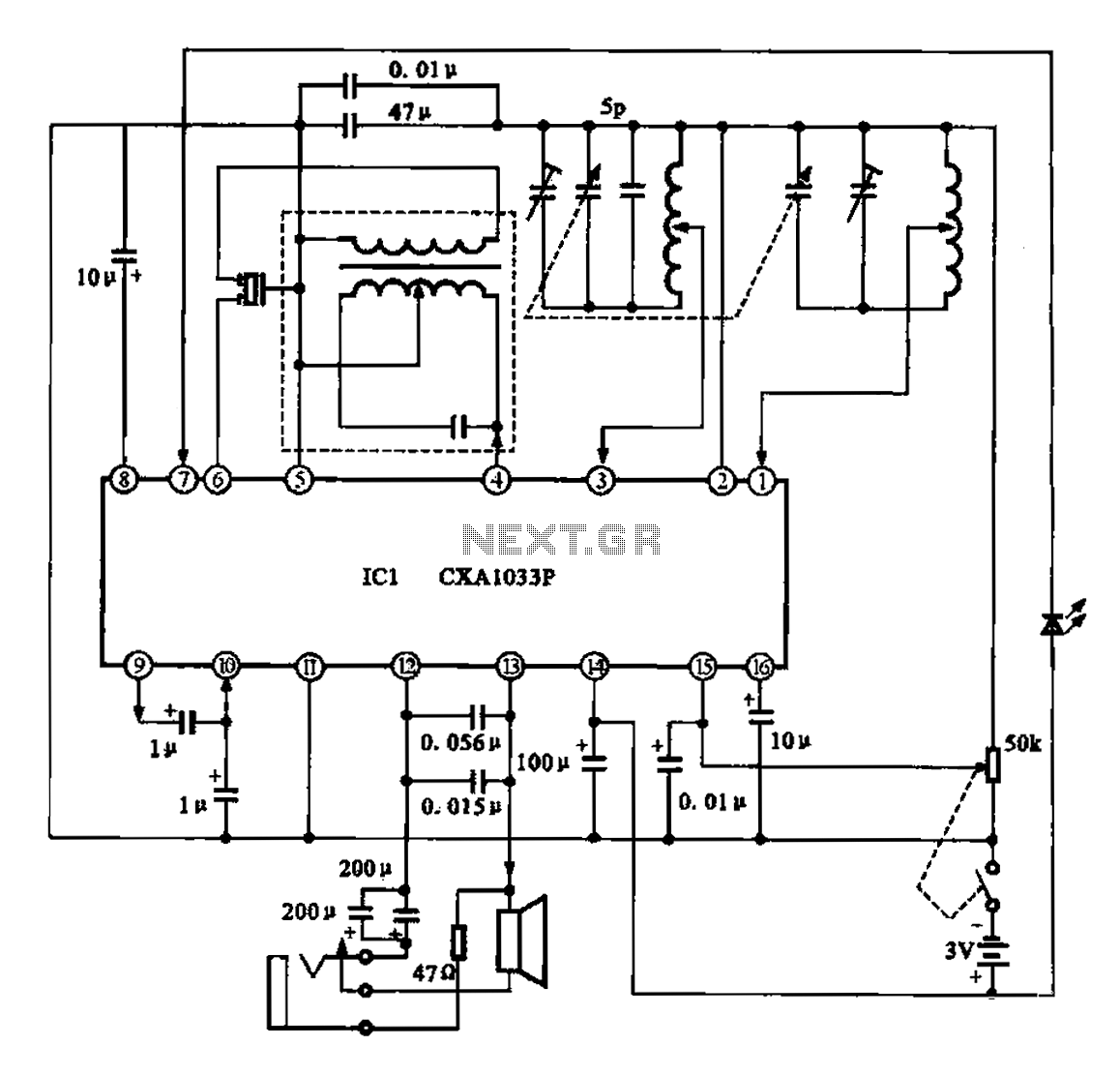
The AM radio features a monolithic circuit design. The broadcast signal is received by an antenna, which feeds into a high-efficiency mixer. The output from the intermediate frequency (IF) transformer undergoes filtering before being sent to the IC1. The...
Gain adjustment can be made more flexible when controlled by a voltage signal, as this allows for various methods to provide a user interface. The concept of voltage-controlled gain adjustment is integral to many electronic circuits, particularly in audio processing...