
Car-Bulb Flasher circuit

The circuit utilizes a power MOSFET to control the flashing operation of the car bulbs. The MOSFET acts as a switch that rapidly turns the bulbs on and off, creating a flashing effect. When designing this circuit, the specifications of the MOSFET must be carefully selected to ensure it can handle the voltage and current required by the 12V 21W bulbs.
To construct the circuit, the following components are necessary: a power MOSFET, resistors, capacitors, and a timer or oscillator circuit to generate the flashing frequency. The timer circuit can be built using a 555 timer IC configured in astable mode, which will provide a square wave output to the gate of the MOSFET. The duty cycle of the timer can be adjusted by varying the resistor and capacitor values, allowing for customization of the flashing rate.
The power supply for the circuit should be a 12V source capable of providing sufficient current to drive the bulbs. Proper heat sinking for the MOSFET is essential to prevent overheating during operation, especially when driving high-wattage bulbs.
In applications such as road and traffic alerts, the flashing lights can be mounted on vehicles or stationary posts to enhance visibility. The circuit's simplicity and effectiveness make it an ideal solution for various scenarios where powerful illumination is needed without access to traditional power sources.This astonishingly simple circuit allows one or two powerful 12V 21W car bulbs to be driven in flashing mode by means of a power MosFet. Devices of this kind are particularly suited for road, traffic and yard alerts and in all cases where mains supply are not available but a powerful flashing light are yet necessary..
🔗 External reference
Related Circuits

This design circuit is for audio graphic equalizers, which are commonly found as commercial products, yet published circuits for them are quite rare. The circuit features a simple design that requires an operational amplifier (op-amp) to amplify the input...

This solar charge controller integrates multiple features into a single design, including a 3A current rating, low dropout voltage (LDO), and a range of voltage adjustment capabilities. The solar charge controller is a critical component in solar energy systems, tasked...
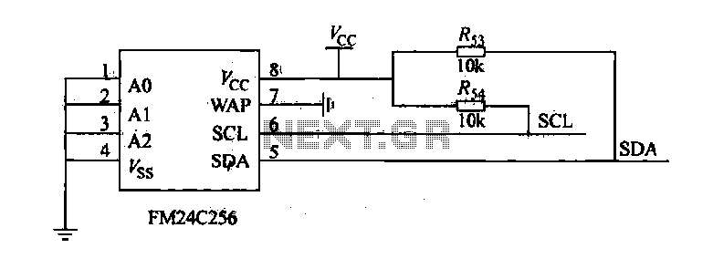
The FM24C256 is utilized as a slave interface circuit in an I2C bus configuration, with the address format specified in Table 27-3. The address pins A2, A1, and A0 are set to low; however, for extended storage capacity, adjustments...

The schematic includes programmable AVRs. For other members of the AVR family or additional programmable ICs compatible with Ponyprog, there is a J1 connector (CON10) that facilitates hardware expansion of the programmer. Additional information about compatible ICs can be...

Bridge circuits are widely used for conditioning signals from resistive sensors. These circuits are sensitive to minor changes in resistance, providing a differential output from a single current or voltage source. However, the sensors connected to a passive bridge...

The circuit presented is a 555 timer-based alarm system for vehicles, which primarily consists of a 555 timer and a quad 2-input NAND gate configuration. It is designed to produce a long beep sound when oil pressure is low...