
Radio Controlled Electronic Flash
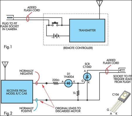
To construct the radio-controlled electronic flash system, the following components are required: an old R/C car, a flash extension cord, a silicon-controlled rectifier (SCR), and necessary wiring tools. The R/C car should be disassembled to access the motor leads. The leads must be identified and marked for polarity, ensuring correct connections during assembly. The flash extension cord is cut and prepared for integration with the transmitter and receiver circuitry.
The transmitter circuit involves connecting the flash extension cord to the control button contacts. This can be done by soldering directly to the contacts or by cutting one of the battery leads and inserting the extension cord into the gap. It is crucial to permanently activate the remote button to maintain functionality.
In the receiver circuit, the SCR is the primary component that allows the flash to be triggered. The normally negative lead from the motor connects to the gate of the SCR, while the normally positive lead connects to the cathode. Upon activation of the transmitter, the SCR switches on, allowing current to flow and triggering the flash.
For mounting, Veroboard can be utilized to secure the SCR and any additional components needed for the receiver circuit. This setup can be housed in the original motor compartment of the R/C car or in a jiffy box for a neater appearance. Care must be taken to ensure that the positive wire from the flash extension cord connects to the SCR's anode, as incorrect connections can lead to malfunction.
Overall, this project combines basic electronics and creativity, allowing photographers to enhance their shooting capabilities with a wireless flash system. Proper attention to detail during assembly and testing will ensure reliable operation in various photographic scenarios.A radio controlled electronic flash is a useful item in any photographer`s kit. Professionals use them all the time. For example, a wedding photographer would put one behind the bride to back-light her gown and veil. You don`t want wires showing in a shot like that. To build this control you will need an old R/C car (the simplest sort) in which th e car runs in reverse at switch-on and goes ahead only when the remote is operated. They can be picked up cheaply as school fetes and garage sales. A typical car will run from 3V (two cells) and use 9V in the transmitter. Before proceeding, make sure that the electronics in the car are operating. It doesn`t matter if the wheels are broken or the motor is dead. You need to gain access to the leads to the motor. Normally (ie, without the remote operating), one is positive with respect to the other. Label them accordingly. On pressing the remote button, the polarity of the motor leads should swap. You will also need a flash extension cord you can cut into two sections. At the transmitter, the camera end of the extension cord is fed into the case and soldered to the control button contacts, as shown in Fig. 1. The contacts are in series with the battery supply, so if you don`t want to open the transmitter, just cut one of the battery leads and connect the flash extension cord into the gap so created.
You will then need to tape down the remote button so that it is permanently operated (ie, closed). All that needs to be done at the receiver end is to connect the normally negative motor lead to the gate circuit of an SCR, as shown in Fig. 2, while the normally positive lead goes to the cathode of the SCR. Now, when the transmitter is operated by the camera`s contacts, the lead polarity is reversed and the SCR acts as a switch to fire a portable electronic flash via the other half of the flash extension cord.
The transmitter can be attached to the camera via a flash bracket or a screw into the tripod socket, depending on what is the most convenient arrangement. The added components in the receiver can be mounted on Veroboard and housed in the space where the electric motor was.
If appearance is a primary consideration, the receiver and the added components could be mounted in a standard jiffy box. When connecting the flash end half of the extension cord to the SCR, make sure that it is the positive wire which goes to the anode of the SCR.
Flash cords do not always have the centre wire connected to the centre pin of the plug. The centre pin of the lead on the flash unit will be positive and this must connect to the anode of the SCR via the lead connected to the R/C receiver. 🔗 External reference
Related Circuits
The following circuit illustrates a 14 Watt Compact Fluorescent Electronic Ballast Circuit Diagram. Features: it is similar to a 16 Watt circuit, 14 Watt. The 14 Watt Compact Fluorescent Electronic Ballast Circuit is designed to efficiently drive compact fluorescent lamps...

This design circuit functions to filter out interference signals, ensuring that the signal received from a Morse code station is distinct. The circuit utilizes the earliest mode of radio communications, which employs Morse Code on a continuous wave carrier...
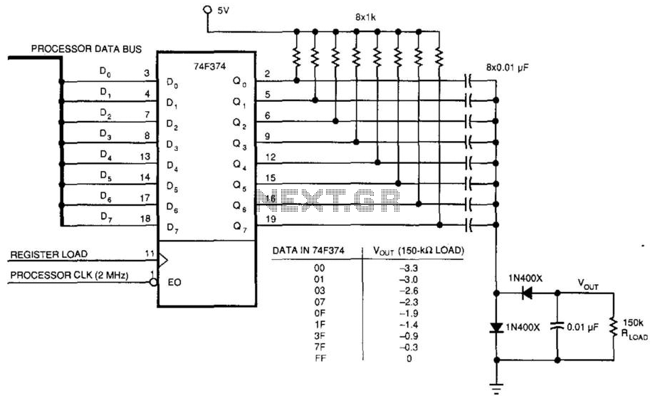
This circuit was used to produce a variable negative voltage for contrast control of an LCD display. A 74F374 generates a square wave that is AC coupled to a rectifier and load. By using the microprocessor clock and data...
Here's something that has always bugged me: light waves are about 5000 Angstroms in wavelength, while atoms are more like 1 Angstrom across. Atoms are thousands of times smaller than light waves, yet atoms obviously interact very strongly with...
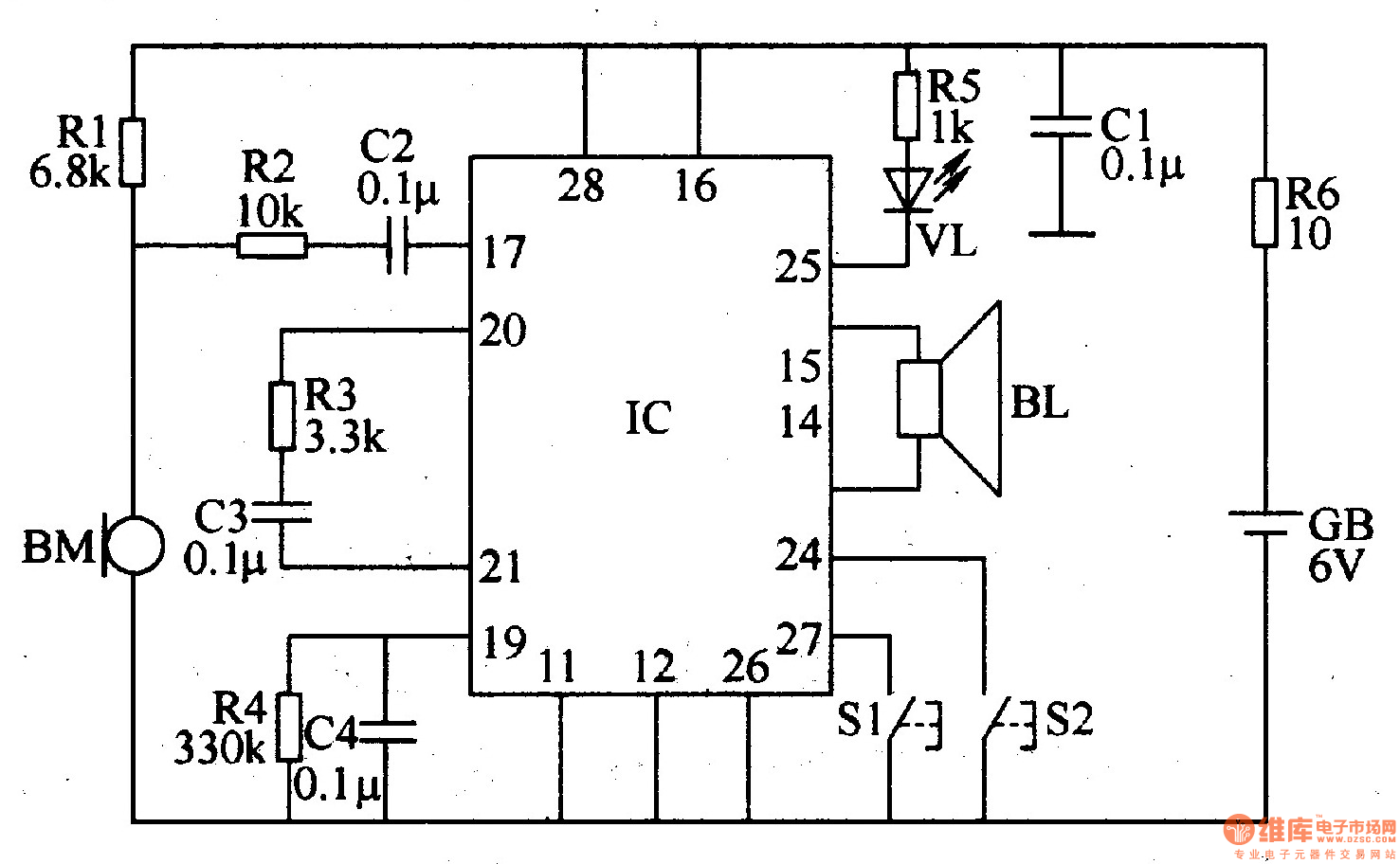
The recordable electronic doorbell consists of a recording and playback integrated circuit (IC), resistors R1-R6, capacitors C1-C4, a microphone (BM), a speaker (BL), control buttons S1 and S2, a battery (GB), and an LED (VL). Resistors R1-R5 should be...
Firstly because of the modulation process we generate at least two copies of the intelligence plus the carrier. For example consider a local radio station transmitting on say 900 Khz. This frequency will be very stable and held to...