
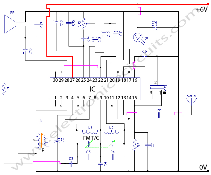
Radio Direction Finder
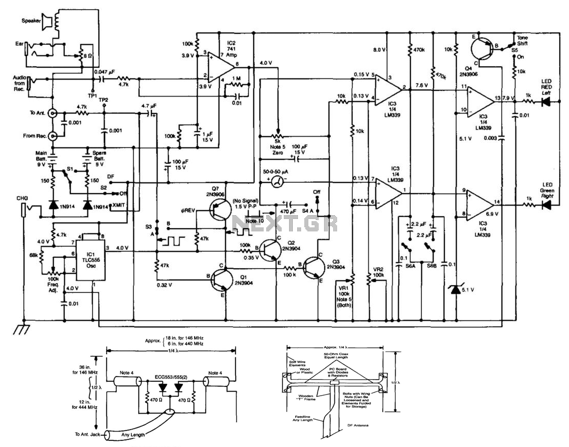
The RDF (Radio Direction Finding) circuit is designed to facilitate the detection of the direction of incoming radio signals by utilizing a square-wave oscillator (IC1). This oscillator generates a square wave that alternately switches two antennas, allowing for the evaluation of the strength of signals received from different directions at an audio frequency. The output from the antennas is fed into a phase detector consisting of transistors Q1, Q2, Q3, and Q7. This phase detector plays a critical role in comparing the amplified output from the receiver (amplified by IC2) with a reference phase generated by IC1.
The phase comparison yields a signal that indicates the relative phase difference between the incoming signal and the reference, which is essential for accurately determining the direction of the source of the radio waves. The results of this comparison are then translated into a visual indication using a 50-meter scale, which serves as a left-right indicator, allowing the user to discern the directionality of the signal effectively.
In conjunction with these components, IC3 functions as a comparator that drives indicator LEDs, providing a clear visual representation of the phase detection results. The LEDs illuminate based on the output from the phase detector, offering immediate feedback to the user regarding the direction of the incoming signal. This combination of oscillation, amplification, phase detection, and visual indication forms a comprehensive RDF circuit capable of accurately determining the direction of radio frequency sources. This RDF circuit consists of a square-wave oscillator (IC1), which switches two antennas alternately at an audio rat e. A phase detector (Ql, 2, 3, 7) is used to compare receiver output amplified by IC2 with the reference phase from IC2 with the reference phase from IC1. 50- meter is used as a left-right indicator. IC3 is a comparator used to drive indicator LEDs. 🔗 External reference
Related Circuits
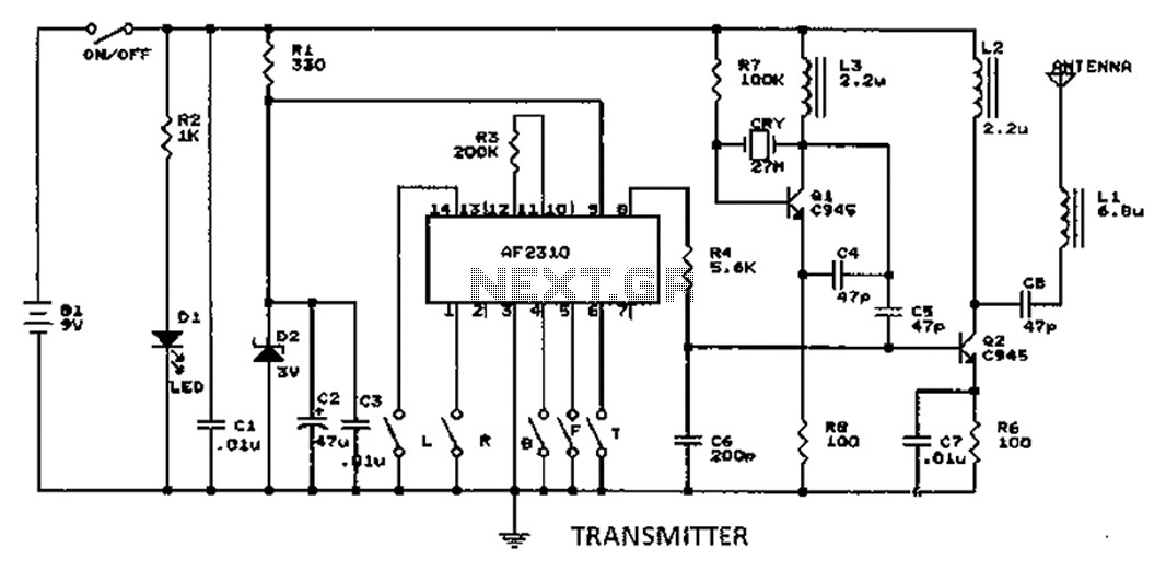
A radio control circuit designed for controlling small motors, similar to a car radio remote control toy, offers seven functions: forward, backward, left, right, left behind, right behind, and stop. The circuit requires a 27.9 megahertz frequency and a...
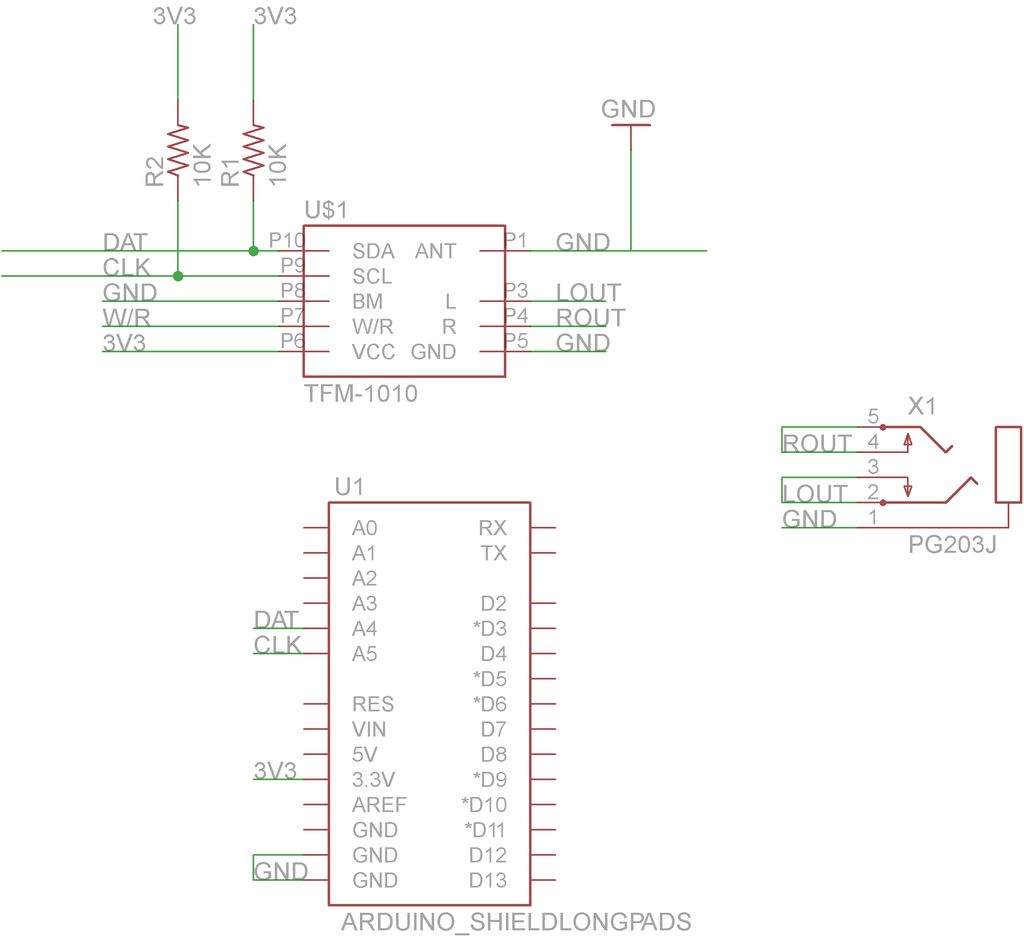
This guide will demonstrate how to construct a custom FM radio receiver shield compatible with an Arduino board. The radio chip utilized in this project is the AR1010, which can be sourced from Sparkfun or Electrokit. Code for initializing...
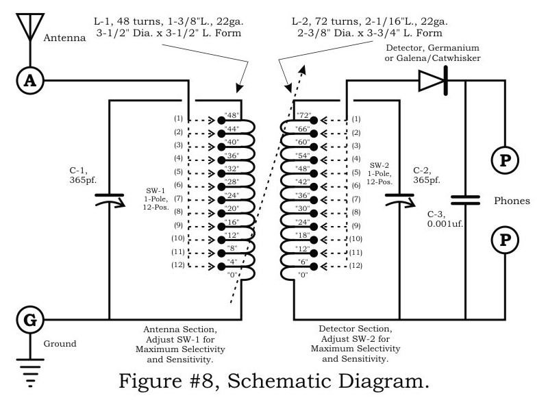
A two-circuit tuner, similar to a loose coupler, is an effective method for achieving selectivity without compromising sensitivity. The circuit introduces the signal to the primary antenna section via the SW-1 arrangement, allowing the antenna to be matched to...
CXA1019 FM RADIO CXA1019 is a one-chip FM/AM radio IC designed for radio-cassette tape recorders and headphone tape recorders, and CXA1019S has the... The CXA1019 is an integrated circuit (IC) specifically engineered for FM/AM radio applications, particularly within radio-cassette tape...
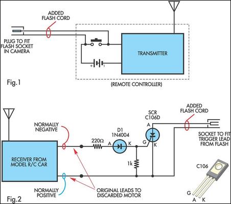
A radio-controlled electronic flash is an essential tool for any photographer's kit, frequently utilized by professionals. For instance, a wedding photographer may position one behind the bride to illuminate her gown and veil without visible wires in the shot....
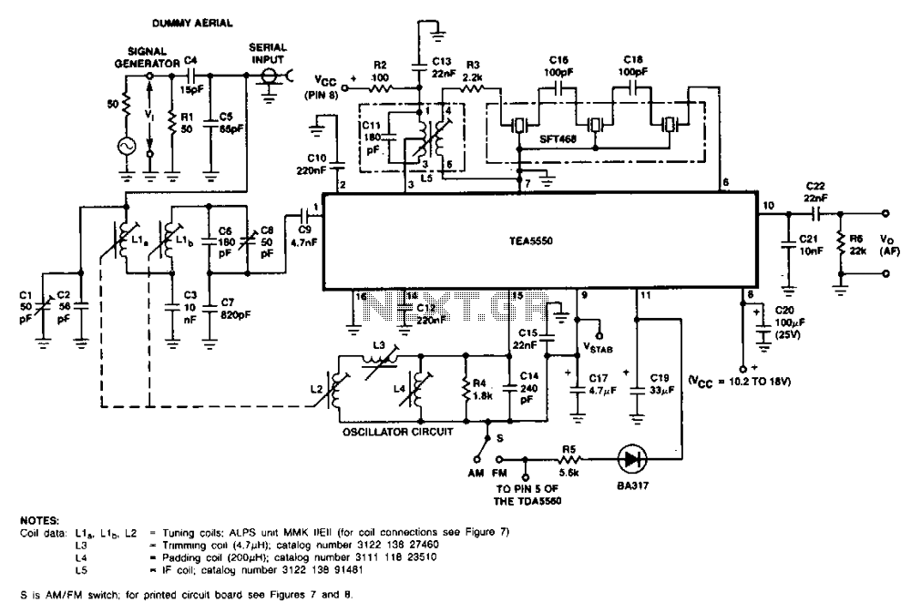
Coil data L1 0, L10, L2 = Tuned CQ<Is: ALPS unit MMK IIEII (for coil connections see Figure 7), L3 -Tuning coil (4.71 µH), L4. Padding capacitor (20 pF), L5. IF Coil. More: This circuit diagram is for a double-tuned, AM-channel, in-car radio receiver using the TEA5550. The described circuit diagram represents a double-tuned AM radio receiver designed for in-car applications, utilizing the TEA5550 integrated circuit. This configuration is particularly effective for enhancing the selectivity and sensitivity of AM signals, making it suitable for automotive environments where interference can be prevalent. The circuit features several critical components, including: 1. **Coil L1, L10, and L2**: These coils are essential for tuning the radio to specific frequencies. The tuning is facilitated by the use of a tuned circuit, which helps in filtering the desired AM signal from the surrounding noise. The designation "Tuned CQ<Is: ALPS unit MMK IIEII" suggests the use of a specific type of coil or inductor that is optimized for this application. The connections for these coils are referenced in Figure 7 of the documentation. 2. **L3 - Tuning Coil (4.71 µH)**: This inductor plays a pivotal role in the tuning process, allowing the circuit to resonate at the desired frequency. The value of 4.71 µH indicates a specific inductance that is crucial for achieving the correct resonance with the associated capacitors. 3. **L4 - Padding Capacitor (20 pF)**: The padding capacitor is used to adjust the overall capacitance in the tuning circuit, which aids in fine-tuning the receiver's frequency response. A value of 20 pF is appropriate for the tuning range of AM frequencies, ensuring that the circuit can effectively filter and amplify the incoming signals. 4. **L5 - IF Coil**: The Intermediate Frequency (IF) coil is responsible for processing the signal after it has been demodulated. This component is vital for further amplification and filtering, allowing the receiver to extract audio signals from the modulated carrier wave effectively. The use of the TEA5550 integrated circuit is noteworthy, as it is designed for low-power applications, making it suitable for automotive use. Its architecture allows for easy integration with the tuning and amplification stages of the radio receiver, providing a compact and efficient solution for in-car audio systems. Overall, this circuit design emphasizes the importance of precise component selection and configuration in achieving optimal performance in AM radio reception, particularly in mobile environments.