
Pulse-Width-Modulated Motor-Speed Control Circuit

The LM317 adjustable voltage regulator is a versatile component widely used in electronic circuits for voltage regulation. In this configuration, the LM317 is employed to manage the output voltage supplied to a load, which can be either a miniature DC motor or a small lamp. The output voltage can be adjusted by varying the resistance of R3, which sets the maximum voltage limit. The switch SI allows for temporary adjustment of R3 without disrupting the operation of the circuit.
The operation of this circuit relies on pulse width modulation (PWM) to control the effective voltage and current reaching the load. By adjusting R4, the duty cycle of the PWM signal can be modified, thus controlling the average power delivered to the load. This method is efficient for varying the speed of a DC motor or the brightness of a lamp, as it minimizes energy loss compared to linear regulation.
The LM317 has a maximum output current rating of 1 A, making it suitable for small loads. To ensure reliable operation, it is crucial that the load connected to the circuit does not exceed this current limit. Moreover, the LM317 generates heat during operation, particularly at higher output currents. Therefore, the use of an adequately sized heatsink is essential to prevent thermal shutdown and ensure the longevity of the regulator.
In summary, this circuit provides a practical solution for applications requiring adjustable voltage control, making it ideal for small DC motors and lamps, while emphasizing the importance of current limitations and thermal management. Connected in this manner, an LM317 1-A adjustable-voltage regulator can be used to control the speed of a miniature dc motor or vary the brilliance of a small lamp. The circuit does so by controlling the pulse width, and therefore the current, to the load device. To set the desired maximum output voltage, momentarily close SI and adjust R3. Connect either a lamp or small dc motor (as is shown in the schematic to the circuit`s output) and adjust R4 for the desired results.
Any device that is driven by this circuit should have a current requirement of 1 A or less. And you should be sure to use good-sized heatsink for the LM317 regulator IC.
Related Circuits

This is a design schematic for sensing the electromagnetic field. The circuit is built using a 741 operational amplifier (op-amp) IC. It can detect electromagnetic fields, including those from hidden wiring. A 1mH inductor is employed for sensing the...
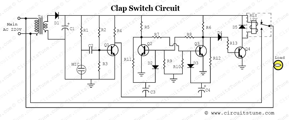
This is a simple electronic circuit for a clap switch project. It is suitable for beginner electronics learners who enjoy experimenting with new projects. The circuit can turn on or off a 220V electronic device, such as a fan...
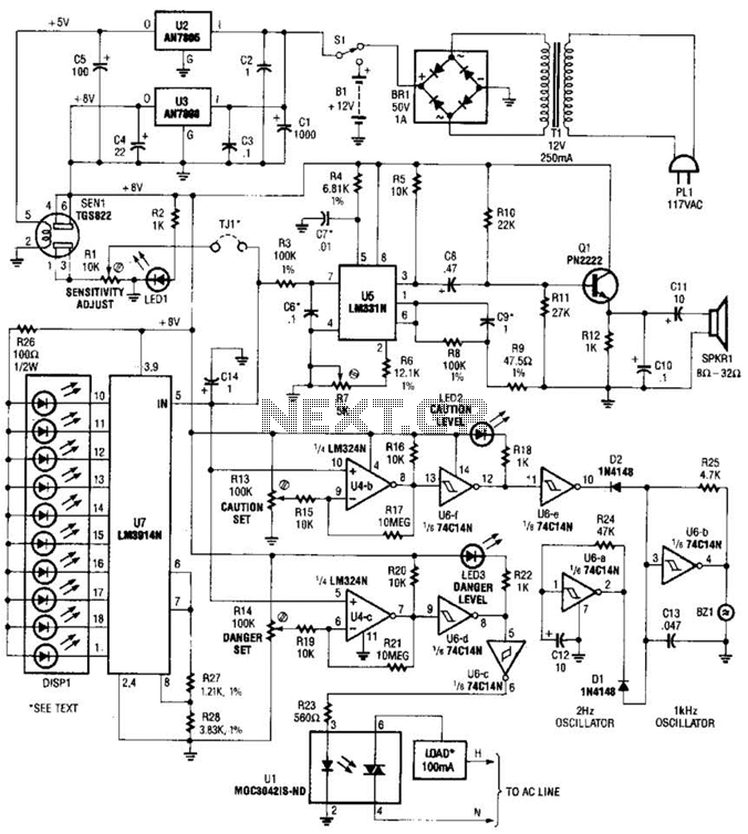
A gas sensor (TGS823 from Allegro Electronics, Cornwall Bridge, CT 06754) conducts in the presence of explosive gases. U5 is a voltage-to-frequency converter that produces a frequency proportional to the sensor conductance. The output frequency ranges from 100 Hz...
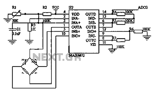
This circuit utilizes a BP01-type pressure sensor and the MAX4472 operational amplifier. The BP01 pressure sensor is specifically designed for blood pressure detection and is primarily used in portable electronic sphygmomanometers. It features a precision thick film ceramic chip...
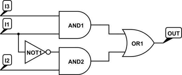
There are integrated circuits that contain AND, OR, and NOT gates. The inquiry revolves around the existence of a single chip that encompasses all the required logic gates. If such a chip does not exist, specific alternatives should be...
This circuit illustrates a flip-flop timer circuit diagram utilizing the 4017 integrated circuit (IC). The key feature includes a push-button switch (S1) that discharges capacitor (C1) through resistor (R2). The 4017 decade counter IC is commonly used in timer and...