
tv remote control jammer
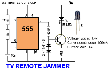
The circuit operates by continuously emitting a modulated infrared signal at a frequency of 38 kHz, which is the standard frequency used by many remote control devices. This modulation is essential for effectively confusing the TV's infrared receiver. The IR emitter diode is driven by a transistor that is configured to switch on and off rapidly, creating the necessary modulation. The two 1N4148 diodes are connected in such a way that they limit the current through the IR LED, ensuring that it operates within safe parameters and prolongs its lifespan.
The choice of the resistor value (5.6 ohms) is critical as it helps to set the appropriate current level through the circuit to maintain the desired output without overheating the components. The transistor acts as a switch; when activated, it allows current to flow through the IR LED, emitting the infrared light. The circuit can be powered by a standard DC power supply, with careful attention given to the polarity to prevent damage to the components.
Overall, this circuit serves as an effective tool for creating a localized interference with infrared signals, making it particularly useful in situations where uninterrupted viewing is desired. It is important to note that while this circuit can provide temporary relief from unwanted channel changes, it should be used responsibly and ethically, as it interferes with the intended functionality of remote-controlled devices.This circuit confuses the infra-red receiver in a TV. It produces a constant signal that interferes with the signal from a remote control and prevents the TV detecting a channel-change or any other command. This allows you to watch your own program without anyone changing the channel ! The circuit is adjusted to produce a 38kHz signal. The IR dio de is called an Infra-red transmitting Diode or IR emitter diode to distinguish it from a receiving diode, called an IR receiver or IR receiving diode. (A Photo diode is a receiving diode). There are so many IR emitters that we cannot put a generic number on the circuit to represent the type of diode.
Some types include: CY85G, LD271, CQY37N (45 ), INF3850, INF3880, INF3940 (30 ). The current through the IR LED is limited to 100mA by the inclusion of the two 1N4148 diodes, as these form a constant-current arrangement when combined with the transistor and 5R6 resistor. 🔗 External reference
Related Circuits
The WS2512-TR1G is a Wide-band Code Division Multiple Access (WCDMA) Power Amplifier (PA) designed as a fully matched 10-pin surface mount module, specifically developed for WCDMA handset applications. This power amplifier module operates within a frequency range of 1920-1980...
This remote transmits a tone using an infrared LED. This tone is decoded by the receiver. Since the receiver only activates when it detects the tone, there are no accidental activations. The described circuit involves a remote control system that...
The following circuit illustrates a Bass-Treble Tone Control Circuit electronic diagram based on the LM1035N integrated circuit (IC). Features include a 0.3 Vrms input level, 80 dB signal noise ratio, 75 dB volume control, ±15 dB typical tone control,...
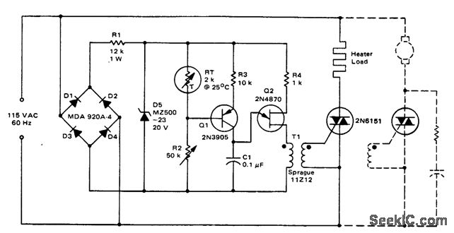
Triac temperature-sensitive heater control. This circuit can be modified to control a motor with a constant load. While the circuit is designed for heating applications, it can also be adapted for cooling by interchanging RT and R2 (courtesy of...
.jpg)
The project outlines a method to add a cost-effective remote doorbell to an existing household doorbell system, particularly useful for individuals who may not hear the doorbell when in the basement. The household doorbell operates on a continuous 24VAC...
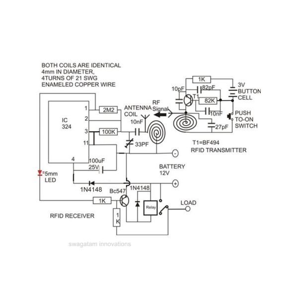
Constructing an RFID access control circuit at home and witnessing its functionality can be a remarkable experience. While the circuit may not be considered high-tech, its low cost combined with the satisfactory results achieved demonstrates a significant level of...
Warning: include(partials/cookie-banner.php): Failed to open stream: Permission denied in /var/www/html/nextgr/view-circuit.php on line 713
Warning: include(): Failed opening 'partials/cookie-banner.php' for inclusion (include_path='.:/usr/share/php') in /var/www/html/nextgr/view-circuit.php on line 713