
Rain Alarm

The rain alarm circuit operates on the principle of detecting moisture through a sensor that can be designed using two conductive plates or probes. When water bridges the gap between these plates, it changes the resistance and allows current to flow, triggering the alarm mechanism. The heart of this circuit is the 555 timer configured in astable mode, which continuously oscillates between high and low states.
In this configuration, the 555 timer's output can be connected to a speaker or an LED to indicate the presence of water. The frequency of oscillation is determined by the resistors and capacitors connected to the 555 timer, allowing for customization of the alarm tone or visual indication.
To build the circuit, the following components are typically required:
- A 555 timer IC
- Two conductive probes for the moisture sensor
- Resistors (typically in the range of kilo-ohms)
- A capacitor (usually in the microfarad range)
- A speaker or LED for the alarm output
- A power supply (typically a battery or DC power source)
The probes should be placed in a location where they can effectively detect rainwater. The resistors and capacitor values can be adjusted to set the desired sensitivity and response time of the alarm. When the sensor is activated, the 555 timer switches its output state, activating the alarm and alerting users to the presence of moisture.
Overall, this rain alarm circuit provides a simple yet effective solution for detecting rainfall, making it useful for various applications, including irrigation systems, automated greenhouses, and home safety systems.Rain Alarm. This circuit gives out an alarm when its sensor is wetted by water. A 555 astable multivibrator is used. 🔗 External reference
Related Circuits
Imagine three or four small engines operating on the same track loop while maintaining a safe distance from one another. Many enthusiasts have attempted this with radio-controlled engines, but it often becomes a challenge to keep them separated, especially...

The circuit consists of a small PIC microcontroller, assembly program, and a few other parts to detect a switch closure from an open door, window, or manual push button and then dial the cell phone number, and transmit a...

This document outlines the installation process for a SPY5000 two-way motorcycle alarm on a 1998 Honda CB250 Nighthawk motorcycle. The SPY5000 two-way motorcycle alarm system is designed to enhance the security of motorcycles by providing features such as remote...
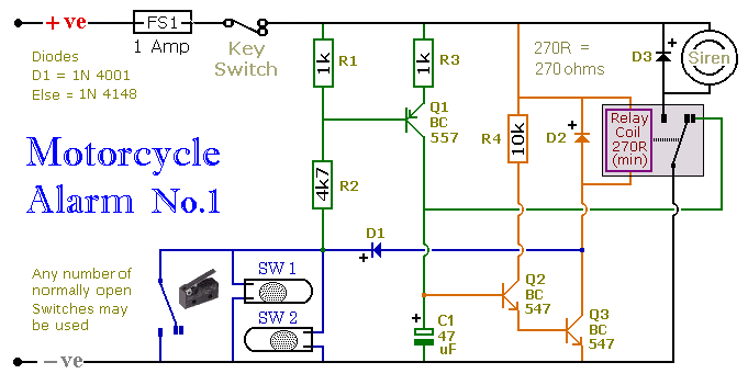
This circuit includes a timed output and an automatic reset feature. It can be manually operated using a key switch or a concealed switch. By incorporating an external relay, the circuit will automatically engage or immobilize the machine each...

The LM1830 fluid detector integrated circuit (IC) from National Semiconductor is designed to detect the presence of fluids using a probe. This chip requires a relatively high supply voltage and is not the most power-efficient option. It is also...
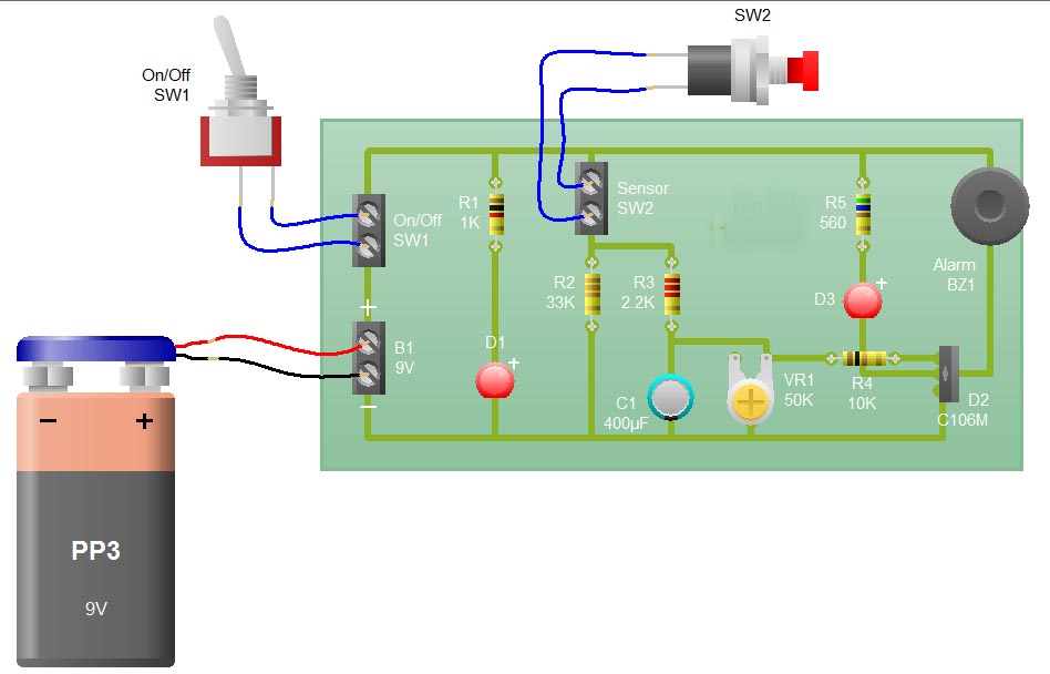
When the sensor switch SW2 is pressed, the LED D3 and the alarm are activated for a certain duration. The timing of the circuit is determined by the resistor R3 and capacitor C1. Additional details regarding the RC circuit...