
Robot Train Cruise Control
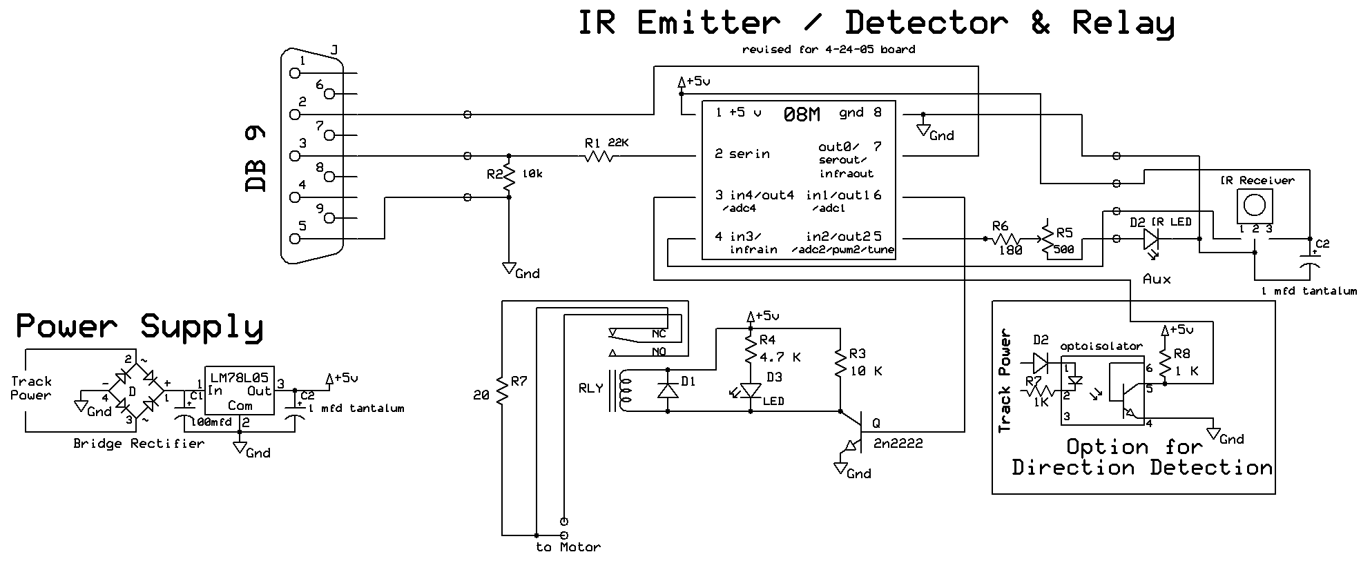
For those interested in constructing this circuit from individual components, the following schematic illustrates a combination of two circuits from the pulsed infrared article. The Picaxe 08M microprocessor generates the 38 kHz pulses sent to the infrared LED (D2). It also monitors the infrared receiver and activates the motor control relay upon detecting a reflected pulse. The power supply section converts track power to a regulated 5 volts, which powers the Picaxe. Further details on power supplies can be found in the article "5 Volt Power for Railway Electronics." An optional section for direction detection is included in the schematic and will be discussed later. The motor speed is regulated by the relay; one of the motor's power connections to the track is interrupted and routed to two contacts labeled "to motor." When the relay is open, these contacts are connected, allowing the motor to run at full speed. Upon detecting reflected infrared light, the relay closes, introducing a 20-ohm resistor in series with the motor, thereby slowing it down. Once the engine moves back far enough, the reflected infrared signal weakens, causing the relay to open and returning the engine to its normal speed, thus preventing abrupt movements.Picture three or four small engines occupying the same loop of track and keeping a safe distance as they go round and round. I am sure that many of us have tried this with radio controlled engines but it can be a constant battle to keep them apart especially if you have many grades to contend with.
Now picture the same group of engines automatical ly keeping their distance from one another, some slowing down as they approach a faster moving train, some speeding up as they are approached from the rear. Combining the pulsed infrared sensor system that was discussed in part III of my series on garden railway sensors ( ) and a simple microprocessor makes this a reality.
You may recall that pulsed infrared sensors react to a beam of infrared light that is pulsed at 38 kHz. The applications in the article mentioned above were all trackside but there is no reason that the sensor and infrared emitter can`t be installed on a moving engine.
An interesting and entertaining application of the circuit described above is to place the reflective IR system on the front of a small, fast moving engine that is running on a track behind another, slower moving engine. With this arrangement is it easy for the trailing engine to determine when it approaches the first train and slow its motor to avoid a collision and to maintain a somewhat constant distance.
A similar technology, called adaptive cruise control, is currently being offered by several auto manufacturers including Ford an GM ( ). It is a modification to cruise control that is designed to keep an automobile a constant distance behind another car.
A recent article by Ralph Walker (Eggliner Collision-Avoidance System ) dealt with this idea using a commercial IR sensor. Although the system worked there were a number of problems associated with it, including high voltage requirements, large size and its not reacting to an external IR beacon.
My version of this system, employing the 38 kHz pulsed IR sensor and a small microprocessor, addresses these problems and has added a stable of rather unique and crowd pleasing engines to my railway. You may recall from the pulsed IR article that an infrared emitter and detector can be placed such that the detector can`t directly "see" the IR emitter but will react to reflected IR pulses.
This type of placement allows us to put both the emitter and detector in the front of an engine so that the detector responds when IR reflects off of the back of an engine as it approaches it. NOTE: The following information is for those of you who might be interested in building this circuit from parts.
For those of you who that would prefer to work with a completed unit or an engine with this system already installed please see the options available at the end of this article. The schematic below shows a combination of two of the circuits from the pulsed IR article. The Picaxe 08M microprocessor generates the 38 kHz pulses that are sent to the IR LED, D2. It also monitors the IR receiver and activates the motor control relay when a reflected pulse is detected.
The power supply section takes track power and converts it to regulated 5 volts to power the Picaxe. More information on power supplies can be found in my article "5 Volt Power for Railway Electronics" ( ). The optional section (lower right in the schematic) for direction detection will be discussed later. The motor speed is controlled by the relay. One of the motor power connections to track power is cut and is run to the two contacts labeled "to motor".
When the relay is open these two contacts are connected and the motor runs at full speed. When the relay is activated on detection of reflected IR the relay contacts close inserting a 20 ohm resistor in series with the motor, slowing it down. When the engine drops back far enough the reflected IR weakens and the relay opens returning the engine to its normal speed.
To avoid extremely choppy movements 🔗 External reference
Related Circuits
This project involves reading a thermistor using an Atmel ATtiny45 or ATMega168 microcontroller to control two fans for cooling a PC housed in a kitchen cabinet. A table is provided for converting the resistance of the BC1482 thermistor to...
S1 and S2 are normally open, push-to-close, momentary switches. The diodes may be red or green and serve solely as indicators of direction. The TIP31 transistors may need to be adjusted based on the motor specifications. It is important...
The circuit operates in such a way that when the patient is typically in an upright position, the SQ mercury switch is turned off, resulting in the alarm circuit being inactive. When the patient lies down, the SQ switch...
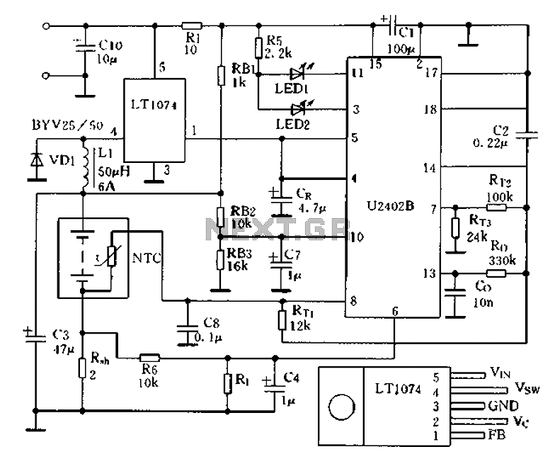
Charging circuit from the DC power supply switching power supply control The charging circuit described is designed to operate with a DC power supply, utilizing a switching power supply control mechanism. This type of circuit is commonly employed in applications...
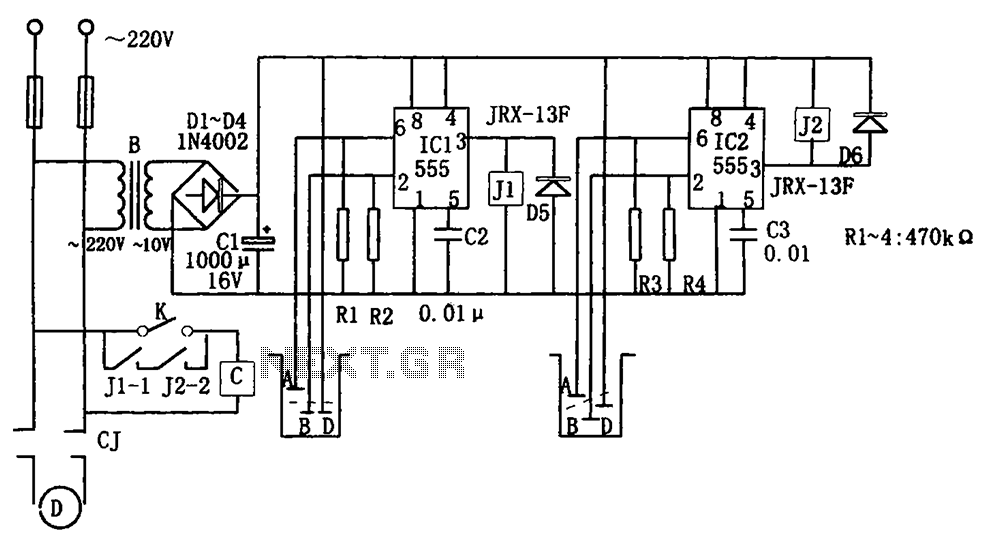
The level control circuit comprises a step-down rectifier circuit, a trigger circuit utilizing two 555 timer ICs (IC1 and IC2), and a relay control circuit. The rectifier circuit is responsible for providing the necessary DC voltage for the flip-flop...
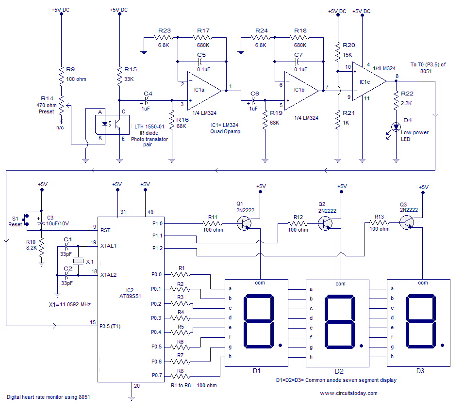
Heart rate monitor using an 8051 microcontroller. It measures the heart rate from the fingertip using an IR diode and phototransistor pair (Photoplethysmography). The AT89S51 microcontroller is utilized in this application. The heart rate monitor circuit operates based on the...