
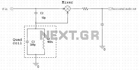
Quadrature FM Detector
The two most common frequency for detection is 455kHz and 10.7MHz.
For the 455kHz, you can use a (Yellow-slug) IF-can as quad-coil. For the 10.7MHz you can use a (Green-slug) IF-can as quad-coil.
Quadrature FM detectors are essential components in demodulating frequency modulated signals. The core functionality relies on the creation of two output signals that are phase-shifted by 90 degrees, which enables the detection of frequency variations in the incoming signal. The high-reactance capacitor (C2) plays a pivotal role in generating these phase-shifted signals.
The LC-tuned circuit, comprising an inductor (L1) and capacitor (C3), is tuned to resonate at the carrier frequency, which is typically set at either 455 kHz or 10.7 MHz for FM detection. This resonance condition is critical, as it allows the circuit to effectively filter and amplify the desired signal while rejecting unwanted frequencies. The phase response of the LC circuit is a key aspect, where the phase angle is zero at resonance. As the frequency of the input signal varies, the phase angle shifts accordingly; it becomes positive for frequencies below 455 kHz and negative for frequencies above this point. This phase shift is directly linked to the frequency deviation of the incoming signal, thus enabling the demodulation process.
In practical applications, the use of specific IF-cans, such as the yellow-slug for 455 kHz and the green-slug for 10.7 MHz, facilitates the implementation of the quadrature detection method. These components are designed to provide the necessary inductance and coupling required for effective signal processing. The output of the quadrature detector, which is an audio signal, exhibits a reasonably linear response for small phase shifts, making it suitable for narrowband FM applications. This linearity is crucial for maintaining audio fidelity and ensuring that the demodulated signal accurately represents the original transmitted information.
Overall, the design and implementation of quadrature FM detectors are fundamental in radio communication systems, enabling reliable reception and processing of frequency modulated signals.Quadrature FM detectors use a high-reactance capacitor (C2) to produce two signals with a 90 degree phase difference. The phase-shifted signal is then applied to an LC-tuned resonant at the carrier frequency (L1 and C3).
Frequency changes will then produce an additional leading or lagging phase shift into the mixer. The diagram at right shows the impedance and the phase of a LC tuned circuit at 455kHz. As you can see, the phase (red curve) is 0 at the resonans. If the frequency is lower than 455kHz then phase angle is positive and if the frequency is higher than 455kHz the phase angle is negative. Conclution: If the frequency changes the phase will also vary and the output voltage (audio signal) to.
For small phase-shift (narrow band FM), the output will be reasonably linear. The two most common frequency for detection is 455kHz and 10.7MHz. For the 455kHz, you can use a (Yellow-slug) IF-can as quad-coil. For the 10.7MHz you can use a (Green-slug) IF-can as quad-coil. 🔗 External reference
Related Circuits
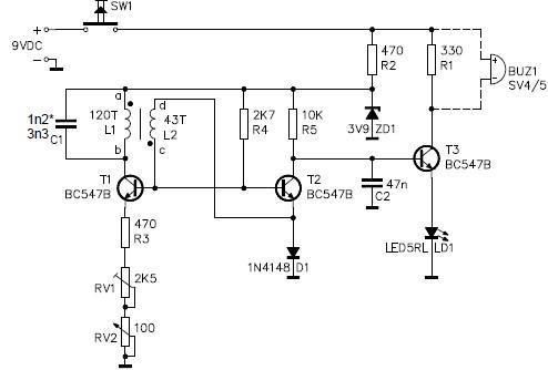
This metal detector circuit project is a simple design based on common electronic components. It utilizes transistors to provide a visual indication through an LED and an acoustic signal to alert users when metal is detected. To calibrate the...
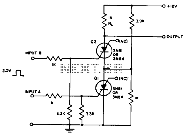
The resistor divider connected between Q1 and Q2 supplies IH to Q1 after input A triggers it. It also prevents the input from triggering Q2 until Q1 conducts. Consequently, the first input pulse after input A is applied will...
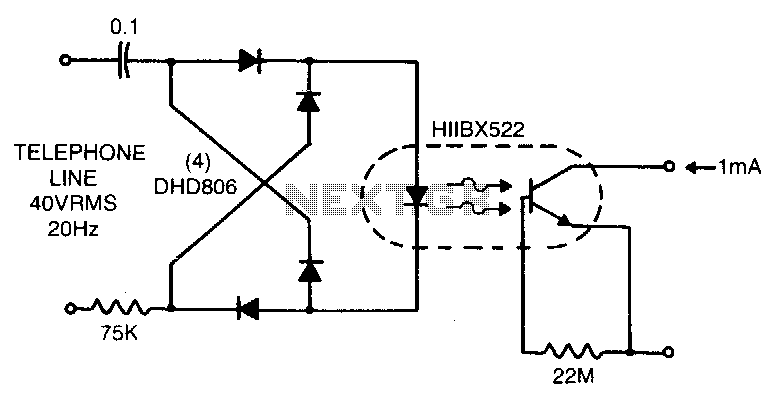
Low line current loading is provided by the H11BX522 photodarlington optocoupler, which delivers a 1 mA output from a 0.5 mA input. The H11BX522 is a photodarlington optocoupler that is designed to provide electrical isolation between its input and output...
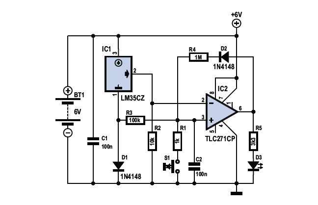
To determine whether it is freezing, one needs to measure the temperature accurately. This requires a reliable temperature sensor. The LM35CZ sensor, which operates within a range of -40 to 110 °C, is suitable for this purpose. It is...
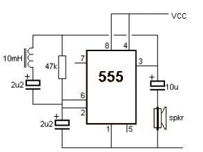
This metal detector electronic project schematic circuit is designed using a simple 555 timer integrated circuit. The schematic circuit requires a few external electronic components. The metal detector circuit utilizes the 555 timer IC in astable mode to generate a...
The core component of this DIY metal detector circuit is the CS209A integrated circuit (IC). The metal detector is constructed using a single 100µH coil, which has a diameter of 40 mm. The CS209A IC serves as the primary signal...