
RAPID BATTERY CHARGER FOR ICOM IC 2A
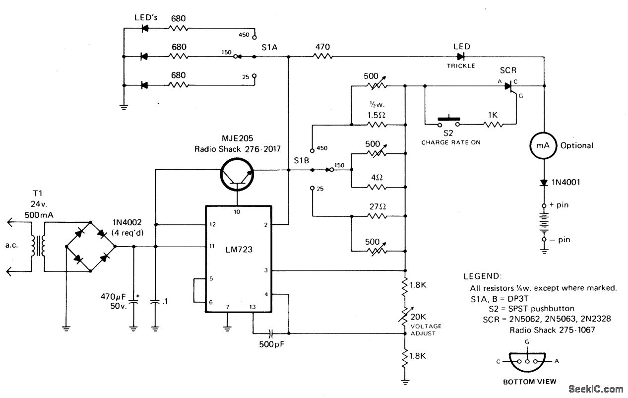
The circuit design begins with a 24 Vac transformer, which steps down the voltage to a manageable level suitable for rectification. The output from the transformer is then rectified using a bridge rectifier or a full-wave rectifier configuration, which converts the alternating current (AC) into direct current (DC). The rectified output is smoothed using a filter capacitor to reduce ripple voltage, providing a more stable DC voltage to the next stage.
The LM723 voltage regulator is utilized to maintain a constant output voltage. This adjustable voltage regulator can be set to provide a specific output voltage by configuring external resistors. In this application, it is paired with an NPN pass transistor, which acts as a current amplifier, allowing for higher current output than the LM723 can provide alone. This configuration is particularly useful for applications requiring a stable and regulated power supply for charging batteries.
The inclusion of the 470-ohm resistor plays a critical role in controlling the initial charging current. When the system is powered on, this resistor limits the trickle charge to the connected battery, preventing damage from excessive current. The momentary pushbutton switch (S2) serves as a manual activation mechanism; when pressed, it triggers the silicon-controlled rectifier (SCR) to conduct, allowing a higher charging current to flow through the battery.
The SCR is a key component in this circuit, providing controlled rectification. Once triggered by the pushbutton, it allows current to flow through the resistor network, which has been designed to limit the charging current to a safe level. This network ensures that the battery charges efficiently without overheating.
Safety is further enhanced by the thermal cutout circuit integrated within the battery pack. This circuit monitors the temperature of the battery during charging. If the temperature exceeds a predetermined threshold, the thermal cutout opens, effectively turning off the SCR and halting the charging process. This feature is essential for preventing battery damage and ensuring safe operation.
Overall, this circuit design effectively combines rectification, voltage regulation, and current limiting to provide a reliable charging solution for batteries, with built-in safety mechanisms to protect against overcurrent and overheating conditions.Rectifted and filtered voltage from the 24 Vac transformer is applied to the LM723 voltage regulator and the npn pass transistor set up for constant current supply. The 470 ohm resistor limits trickle current until the momentary pushbutton (S2) is depressed, the SCR turns on and current ftows through the previously determined resistor network limi
ting the charging current. The SCR will turn off when the thennal cutout circuit inside the battery pack opens up. 🔗 External reference
Related Circuits
This battery allows the indicator to the car battery voltage monitor. The indicator has four LEDs which indicate power. The more LEDs, the higher the voltage. The last LED is a flashing LED. It comes on when the accuspaning...
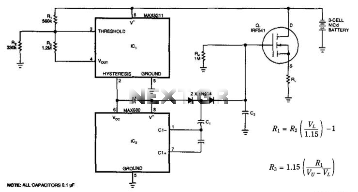
At a predetermined level of declining terminal voltage, the circuit disconnects the battery from the load and halts potentially destructive battery discharge. Q1, a high-side, floating-source MOSFET, acts as the switch. The overall circuit draws about 500 µA when...
The Accu charger circuit is straightforward and simple to construct, requiring no more than ten components. In addition to its ease of assembly, this charger circuit is also cost-effective and highly efficient. The circuit requires a power supply from...
Switching to alternative power sources can help reduce electricity bills. The photovoltaic module or solar panel described here is capable of generating renewable energy. The photovoltaic module, commonly known as a solar panel, is a device that converts sunlight into...
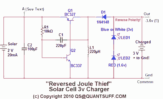
This design presents an innovative approach to the Joule Thief (JT) circuit typically utilized in garden lights. Instead of directly charging a 1.2V battery from the solar cell and converting the power to operate a 3-volt LED, this circuit...

The battery should charge up to 14 volts. A reading of 10.7 volts indicates that one cell is shorted. A good way to diagnose this further is to look at the water level in the cells. The shorted cell...