
Ratiometric resistance measurement
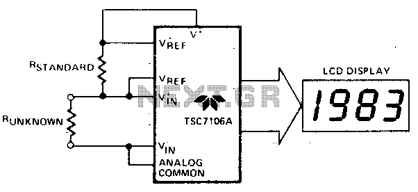
In this circuit configuration, a standard resistor with a precisely known resistance value is used as a reference to measure an unknown resistance. The arrangement involves connecting both resistors in series and passing a constant current through them. The voltage drop across the unknown resistor is measured and compared to the voltage drop across the known resistor.
To implement this circuit, a precision current source is required to ensure that the same current flows through both resistors. The voltage drop across the known resistor can be calculated using Ohm's Law (V = IR), where I is the constant current and R is the resistance of the known resistor. This voltage serves as a reference point for the measurement.
A differential amplifier or an analog-to-digital converter (ADC) can be utilized to measure the voltage across the unknown resistor. The output from the ADC can then be processed to determine the value of the unknown resistance. If the unknown resistance is equal to the known standard resistance, the output display will indicate a value of 1000, which serves as a calibration point for the measurement.
This type of circuit is commonly used in applications requiring precise resistance measurements, such as in laboratory settings or industrial applications where accurate component values are essential. Proper calibration and selection of components are crucial to ensure the accuracy and reliability of the measurements obtained from this configuration.The unknown resistance is put in series with a known standard and a current passed through the pair. The voltage developed across the unknown is applied to the input and the voltage across the known resistor applied to the reference input If the unknown equals the standard, the display will read 1000. 🔗 External reference
Related Circuits
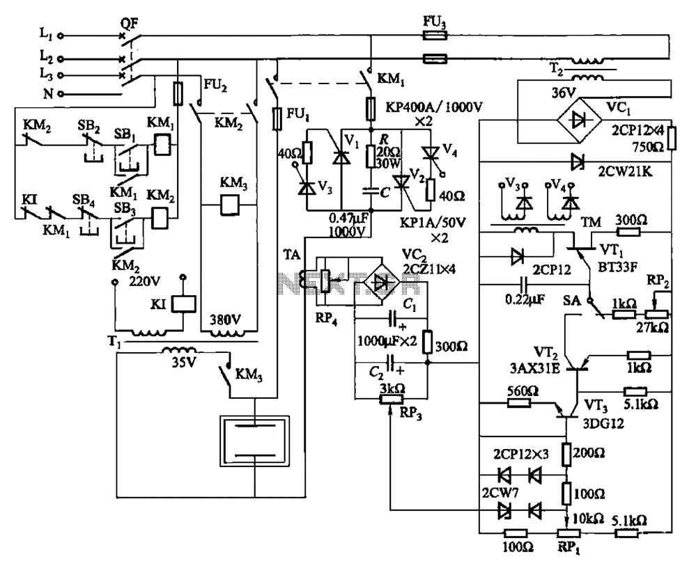
80 kW resistance salt bath furnace control circuit. The salt bath resistance furnace is a high-power device that employs fast start and temperature control technology to significantly save energy. The circuit includes a single-junction transistor (VTi) used as a...
There is growing interest in utilizing PC and workstation platforms for reactive sound synthesis and processing applications. However, few operating systems are designed to provide real-time performance, and vendors typically do not guarantee or specify the expected performance levels...
NI Multisim software provides advanced virtual instruments and analysis tools that enhance the understanding of circuit designs. One such tool, the measurement probe, acts as a functional interface for observing circuit characteristics and customizing the simulation process within Multisim....

Phase noise is a critical performance parameter of frequency synthesizers for wireless applications. RF system designers of phase-modulated cellular systems, such as PHS, GSM, and IS-54, require low noise local oscillator (L.O.) or frequency synthesizer blocks. This document describes...
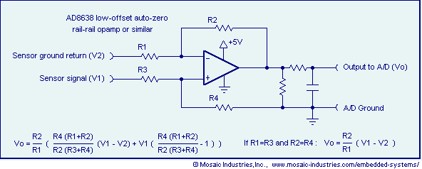
Ground loop offset errors and ground noise are eliminated by a differential amplifier or instrumentation amplifier before the analog-to-digital (A/D) conversion. The differential input amplifier addresses ground loop errors, allowing for precise measurement of non-isolated sensors. A simple operational...

A high-input-resistance operational amplifier (op-amp), a bridge rectifier, a microammeter, and several discrete components are necessary to implement this versatile circuit. This circuit can measure DC, AC RMS, AC peak, or AC peak-to-peak voltage by simply altering the resistor...