
RC Audio Oscillator
The audio oscillator circuit operates on the principle of generating a periodic waveform, typically a sine or square wave, which is essential for various audio applications. The core of the oscillator is often based on a feedback loop that includes active components such as operational amplifiers or transistors, alongside passive components like resistors and capacitors. In this design, the frequency of oscillation is predominantly influenced by the values of the capacitors and resistors used in the circuit.
The 0.01 µF capacitors play a crucial role in determining the timing characteristics of the oscillator. The frequency \( f \) of the oscillator can be approximated using the formula:
\[
f = \frac{1}{2 \pi R C}
\]
where \( R \) is the resistance in ohms and \( C \) is the capacitance in farads. In this design, the 5.6 kΩ resistors work in tandem with the capacitors to set the desired oscillation frequency around 1 kHz. Adjusting the capacitance by replacing the 0.01 µF capacitors with different values allows for fine-tuning of the output frequency, enabling the generation of various audio tones as needed for testing purposes.
The inclusion of an 8-volt regulator is essential for stabilizing the power supply to the oscillator, ensuring consistent performance across different operating conditions. While the specific regulator design is left to the user's discretion, it is advisable to select a low-dropout regulator (LDO) to maintain efficiency, especially if the oscillator is powered from a battery source.
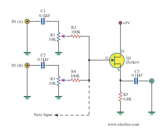
Overall, this audio oscillator circuit is a practical tool for audio testing and development, providing flexibility in tone generation and stability in operation. The schematic serves as a foundational guide, allowing for customization and adaptation to specific testing requirements in audio electronics.Here is the design of an audio oscillator that runs at approximately 1 KHz. I don`t remember where I got this circuit, probably from EMFRD, since Wes`s book is a treasure trove of useful circuits. This handy oscillator can be used as a source of audio for testing out audio stages in receivers and the like, or as a stable signal source for testing
microphone circuits in transmitter. Aschematic of the audio oscillator. What is not shown is the 8-volt regulator circuitry that is part of the finished module. Just use your favorite part and circuitry there, it isn`t critical at all. This view shows a bit more detail of the 0. 01 uF capacitors, the red-orange units in the foreground, used along with the 5. 6K resistors to set the frequency of oscillation. These capacitors can be changed for a higher or lower audio tone. 🔗 External reference
Related Circuits
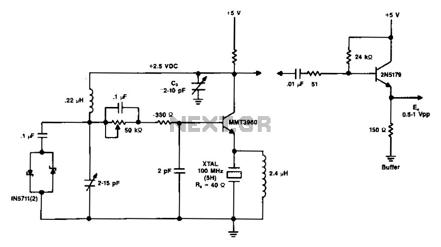
The diagram illustrates a 100 MHz oscillator functioning on the fifth harmonic. To preserve the transistor's gain, it is important to note the increase in the collector's load resistance, Rl, due to the rise in the quartz crystal's internal...
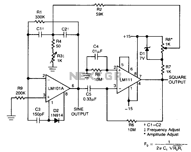
This circuit will provide both a sine and square wave output for frequencies ranging from below 20 Hz to above 20 kHz. The frequency of oscillation can be easily adjusted by changing a single resistor. This circuit is designed to...
This circuit utilizes two quad op-amps to create an eight LED audio level meter. The op-amp employed in this circuit is the LM324, a widely used integrated circuit that is readily available from numerous electronic component suppliers. The 1K...
This is a 25 Watt basic power amplifier designed to be relatively easy to build at a reasonable cost. It offers better performance than the standard STK module amplifiers commonly used in nearly all mass-market stereo receivers manufactured today. The...
The audio from each radio will be connected to the iPod audio output and vice versa. This setup alters the impedance and can affect sound levels, potentially damaging the audio circuits of one or more radios involved. It is...
TIP141 is an NPN silicon power Darlington transistor designed for complementary use with TIP145, TIP146, and TIP147. It can handle up to 125 W at a case temperature of 25 °C, with a continuous collector current of 10 A...