
RC Differentiator
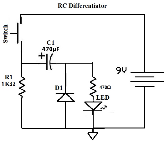
A differentiating circuit is utilized in various applications, particularly in signal processing and timing applications. The circuit operates based on the fundamental principles of capacitive charging and discharging through a resistor. When the circuit is powered, the capacitor C1 charges up to the peak voltage of the input signal. The time constant, represented by the product of R1 and C1, is a critical factor that dictates how quickly the capacitor discharges once the input voltage is removed or reduced.
In practical terms, when the switch is activated, the LED connected in parallel with the capacitor will illuminate brightly due to the initial surge of current from the fully charged capacitor. The LED will remain lit as long as the capacitor discharges through the resistor R1. The exponential decay of the voltage across the capacitor leads to a corresponding decrease in the current flowing through the LED, resulting in a gradual dimming effect.
The circuit can be designed using standard electronic components. For instance, if R1 is set to 1 kΩ and C1 to 1 µF, the time constant will be 1 ms, leading to a rapid fade-out. Conversely, increasing R1 to 10 kΩ or C1 to 10 µF will extend the fade-out duration to approximately 10 ms. This flexibility allows for tuning the circuit to meet specific requirements based on the desired fade-out time.
In summary, the differentiating circuit provides a practical method for controlling the timing and intensity of an LED based on the input voltage characteristics, with the ability to customize the response time through component selection.A differentiating circuit is a circuit that produces pulses or that fades out input waveforms from its peak value all the way down to zero. To show this visually, let`s view the waveforms, which will show the result of this project. So you can see the input that we are putting into the circuit is a DC voltage of 9 volts, which is a straight line a
cross against time. As the output, we get a waveform that first at the peak voltage of 9 volts of the battery but then fades out over time until it goes down to 0. So at the moment when the power switch is set to ON, the wave is at its highest level and then gradually fades out.
In this circuit we are going to be lighting an LED. So at the time we turn the switch ON, the LED will be at its brighest level, since it is receiving the peak voltage at the initial stage but then it will get dimmer and dimmer until it has completely faded out 1 or 2 seconds later. The basic components of the RC type differentiating circuit are R1 and C1. The value of R1xC1 is known as the time constant. With a larger value of R1 X C1, the wave takes a longer time to fade out, so the LED stays on longer.
So R1 and C1 can alter the output waveform. 🔗 External reference
Related Circuits
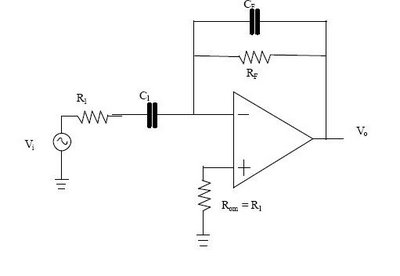
The differentiator circuit is an application circuit derived from mathematical principles influenced by capacitor behavior. The circuit, as illustrated in the accompanying image, is a simple differentiator configuration. To derive the differentiator formula, the following sequence is used: Ic...
This is a differentiator circuit. This circuit can be used to perform differential operations. There are two types of differentiators: the true differentiator and another type. A differentiator circuit is designed to output a voltage that is proportional to the...
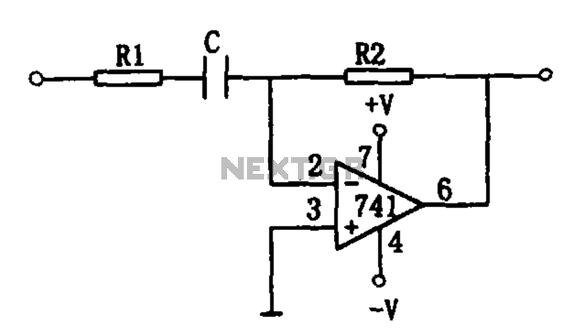
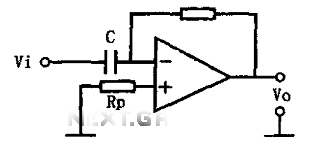
The circuit functions as a differentiating circuit designed for utility applications. It employs an operational amplifier (op-amp) configuration. When a triangular wave is applied as the differential input, the output is a square wave. The frequency of the input...
This circuit illustrates a basic differentiating circuit. The differential operation circuit can process input and output signals, establishing a relationship between the output and the input. A basic differentiating circuit is designed to produce an output that is proportional to...