
Practical differentiator
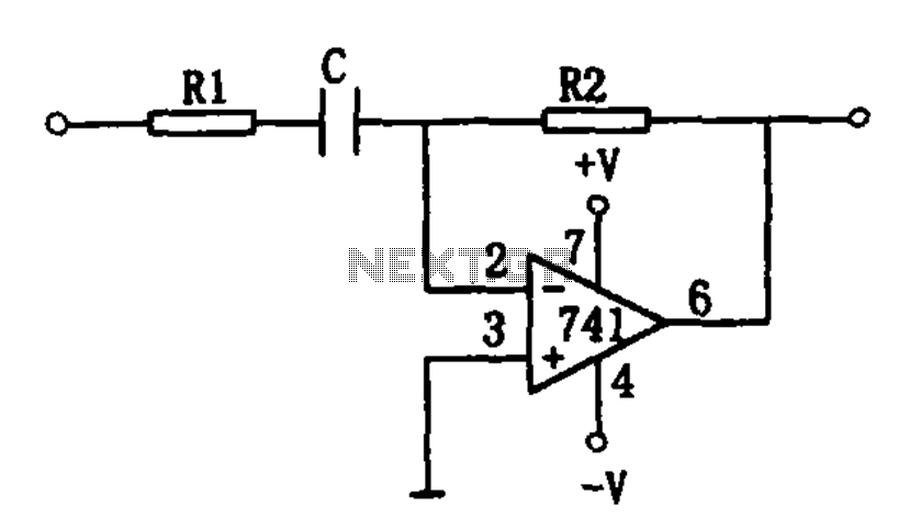
The differentiating circuit utilizes an operational amplifier to convert a triangular wave input into a square wave output. This transformation is achieved through the differentiation process, where the op-amp amplifies the rate of change of the input signal. The circuit design requires careful selection of resistors R1 and R2, as their values directly impact the circuit's frequency response and stability. Specifically, R1 should be ten times the value of R2 to ensure proper functionality.
The capacitor C plays a crucial role in determining the circuit's behavior, as it works in conjunction with R2 to set the time constant of the differentiating circuit. The relationship C = 1/(R2 * fin) indicates that for a given input frequency fin, the capacitor value must be chosen to achieve the desired differentiation effect. Alternatively, if the capacitance is predetermined, R2 can be adjusted according to the formula R2 = 1/(C * fin) to maintain the circuit's operational integrity.
In practical applications, the circuit can be used in signal processing tasks where the conversion of waveform shapes is essential, such as in waveform generators or signal conditioning circuits. Proper implementation of this differentiating circuit requires attention to component tolerances and characteristics to ensure reliable performance across varying input frequencies.Differentiating circuit as shown for the utility. The op amp circuit constituted by Universal. When the differential input a triangular wave, square wave output, while the inpu t signal frequency by the circuit resistors R1, R2 and capacitor C decision. The circuit requires about one-tenth of the value of R1 R2, namely:R1 R2/10 The value of the capacitor C is jointly determined by the R2 value of the input frequency fin, their relationship: C 1/R2fin Similarly, if the known value C, then R. Values calculated by the following formula:R2 1/Cfin
Related Circuits
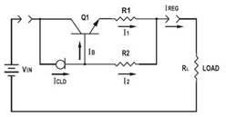
This application datasheet article includes sections that discuss the practical current booster circuit technique, which involves a conventional circuit using a Constant Current Load (CLD) and a current boosting circuit technique. It covers the analysis of the booster circuit...
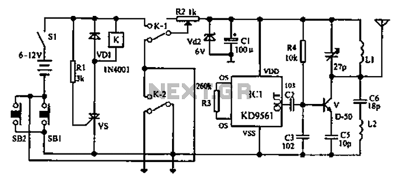
As environmental awareness increases, electric cars have become an essential part of people's transportation. Preventing electric car theft is a significant concern for owners. Various electric vehicle anti-theft locks have been developed; however, theft of electric cars continues to...
The circuit consists of a triggering device, a monostable delay circuit, an alarm sound generator, an audio amplifier circuit, and a light control circuit, with a partially blocking preset circuit and power circuit. When the door is locked and...
A square wave is generated by a 7555 timer operating at a supply voltage of 10V, producing an output voltage of 10V. A single quadrant multiplier (RC4200, Fairchild, obsolete) forms a two-quadrant square root circuit, converting 10V input to...
The inexpensive flashlight utilized a small (0.22 Farad) capacitor for energy storage, which provided approximately 6.6 Joules of energy, significantly less than 1/1000th of the energy contained in a single AA alkaline cell. As a standard "super capacitor," it...
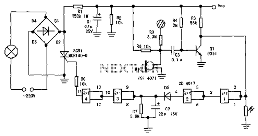
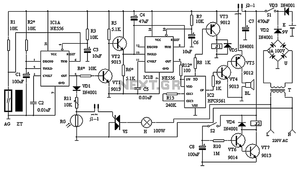
The circuit diagram illustrates a sound, light, and touch-controlled delay self-extinguishing switch. It comprises three main sections: the power circuit, the signal conversion detecting circuit, a delay circuit, and a control circuit. 1. Power Circuit: This section consists of...