
servo motor control through keypad
The process of reading the flash memory of a microcontroller is critical for verifying the integrity of the programming. The microcontroller typically operates in a byte mode where each read operation involves sending a specific instruction to retrieve data from designated memory addresses. The first byte of the instruction serves as an indicator for the type of operation (in this case, a memory read), while the subsequent bytes provide the necessary address information.
In a typical application, the microcontroller is set to operate in programming mode, enabling it to communicate effectively with external devices or programmers. The instructions are structured such that the address space is efficiently utilized, allowing for the retrieval of data from any of the memory locations within the 8K limit. The organization of memory into pages, with each page consisting of 256 bytes, facilitates bulk reading of data, enhancing the speed and efficiency of the programming verification process.
When executing a read instruction, the microcontroller expects a precise sequence of bytes. The second byte indicates the page address, while the third byte may contain additional address information. Once the instruction is received, the microcontroller will respond by transmitting the requested data in a sequential manner, ensuring that the entire block of 256 bytes is sent before accepting any further instructions. This method of operation minimizes errors and maximizes throughput, which is particularly important in applications requiring rapid programming and verification cycles.
Overall, understanding the mechanics of reading flash memory is essential for anyone working with microcontrollers, particularly in debugging and validation scenarios. Proper knowledge of the instruction set and memory addressing scheme is crucial for successful implementation and operation.This tutorial explains how to read the content of the microcontroller `s flash memory. The source microcontroller reads the content of the memory and displays it on the LED s. The content is nothing but the program written in the memory of microcontroller. This step is often used to verify whether microcontroller has been correctly programmed or n ot. If the values which are read from a memory location are same as the one which needs to be written at this particular memory location, then the microcontroller has been programmed correctly. If there is any mismatch, it means microcontroller has not been programmed correctly. The reader should know the basics of sending and receiving the single byte in programming mode. Refer to 8051 Programmer basics before reading this tutorial. In this mode the values are read one by one. You need to send the address of the memory location in every instruction whose value is to be fetched.
The microcontroller in return sends the value which is stored on this location. The first byte of the instruction signifies memory read operation (byte mode). The second and third byte tells the address of the memory location. Some bits of the second byte are don`t care. This is because the maximum size of flash memory for this family is 8K and in order to address the last memory location a maximum of 13 bits is required. The target controller returns the value corresponding to the address during the fourth byte. The memory of the microcontroller is arranged in form of pages. Every page contains 256 bytes arranged in 16 rows and 16 columns. In this mode, a chunk of 256 bytes is read in one read instruction. The second byte of the instruction sends the address of the page to be read. The target microcontroller in return sends 256 consecutive bytes just after the second byte of the instruction.
No instruction is accepted till 265 data bytes are read and if instruction is read it will be considered as data. 🔗 External reference
Related Circuits
The circuit diagram of an IC Controlled Emergency Light with Charger, also known as a 12V to 220V AC inverter circuit, is presented here. This circuit features automatic activation of the light during mains failure and includes a battery...
Modify it to click and latch a relay when the button is pressed from anywhere in the house. Additionally, if possible, unlatch the relay when pressed again. A flip-flop circuit may be created to take the first signal and...

Connect the components, ensuring to pay attention to the connections for the transistor. The 22-ohm load resistor and thermistor should be connected in a manner that allows for good thermal contact. Note: If using the Light Application Adapter, REFIN-...
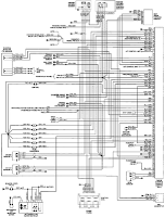
The electrical wiring diagram for the 1993 VW Passat includes the Engine Control Module, Automatic Control Unit, and Automatic Solenoid. This diagram illustrates the connections and wiring between various components of the vehicle's system, such as the multi-function switch,...
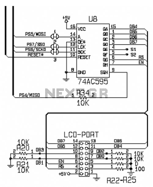
This circuit is designed for interfacing an I/O keypad and an LCD, allowing students to gain hands-on experience with basic I/O device interfacing using the HCS12 microcontroller mounted on the CML12S-DP256 development board. The keypad utilized in this circuit...
The WS2512-TR1G is a Wide-band Code Division Multiple Access (WCDMA) Power Amplifier (PA) designed as a fully matched 10-pin surface mount module, specifically developed for WCDMA handset applications. This power amplifier module operates within a frequency range of 1920-1980...