
Cmos line receiver

The circuit operates as a comparator with a defined trip point, which is established by the resistors R1 and R2. This configuration allows the trip point to be positioned at the midpoint between the positive and negative supply voltages, ensuring balanced operation. The inclusion of resistor R3 introduces hysteresis into the system, effectively providing over 200 mV of feedback that enhances the circuit's noise immunity. This feature is crucial in applications where signal integrity is paramount, as it prevents false triggering due to minor fluctuations or noise in the input signal.
The maximum operational frequency of this circuit is approximately 300 kHz, which indicates its suitability for high-speed applications. For instances where TTL (Transistor-Transistor Logic) level compatibility is required, a modification can be made by replacing R2 with a 39 kΩ resistor. This adjustment alters the trip point, centering it at 1 V, which is optimal for interfacing with TTL logic levels.
In practical applications, this configuration can be utilized in various scenarios, such as signal conditioning, level detection, and pulse-width modulation systems. The circuit's design allows for flexibility in tuning the trip point and hysteresis, making it adaptable to different electronic systems and requirements. By carefully selecting resistor values, one can achieve the desired performance characteristics while maintaining stability and reliability in operation.The trip point is set half way between the supplies by Rl and R2; R3 provides over 200 mV of hysteresis to increase noise immunity. Maximum frequency of operation is about 300 kHz. If response to TTL levels is desired, change R2 to 39 K The trip point is now centered at 1 V.
Related Circuits
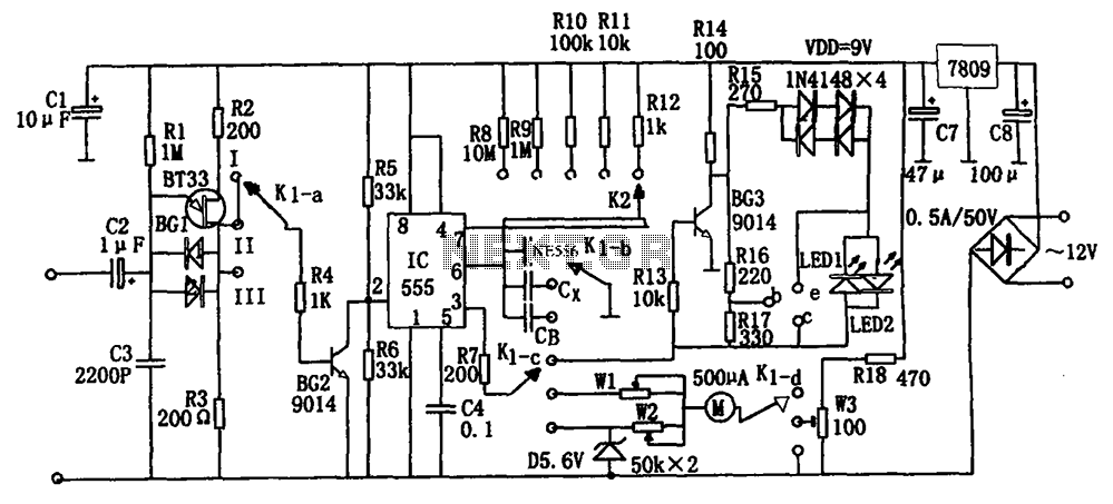
The frequency detection circuit utilizes a transistor line, adjustable via a preset switch K1, to convert capacitance and frequency measurements. The K1 switch is positioned to detect capacitance. The circuit comprises components including a 555 timer, resistors R8 to...
This circuit can manage nine independent telephones using a single telephone line pair, located up to 100 meters apart for making and receiving calls while ensuring conversation privacy. It is particularly useful for multiple members residing in different rooms...
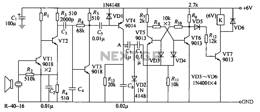
The circuit consists of transistors VT1 through VT7 and other components. Due to the weak signal received from the transmitter, the circuit employs a multi-stage amplifier to enhance the output. This output generates a square wave pulse signal to...
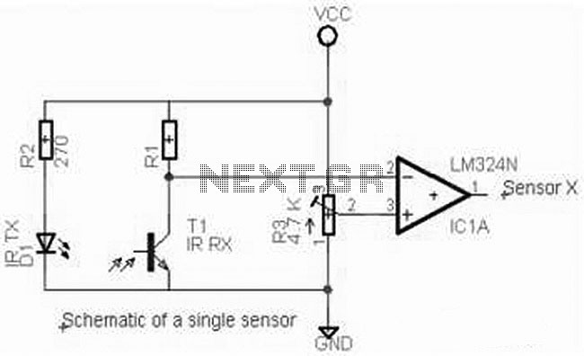
The complete electrical circuit diagram of a line follower robot is based on the ATmega16 microcontroller. This circuit consists of three main modules: the sensor module, the microcontroller module, and the DC motor module. The line follower robot circuit operates...
Most telephone equipment today utilizes a DTMF receiver integrated circuit (IC). A widely used DTMF receiver IC is the Motorola MT8870, which is commonly found in electronic communication circuits. The MT8870 is an 18-pin IC employed in telephones and...
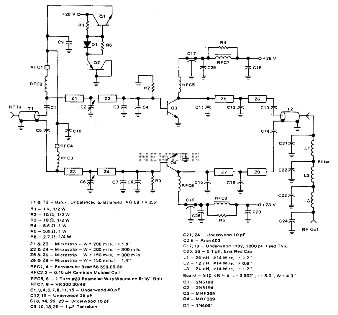
This 100-watt linear amplifier can be built using two MRF309 transistors in a push-pull configuration, requiring only 16 watts of drive power within the frequency range of 420 to 450 MHz. It operates from a 28-volt supply and achieves...