
Reducing Relay Power Consumption
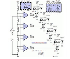
The circuit utilizes a simple microcontroller or a basic timer IC to manage the operation of four relays in a predetermined sequence. The design incorporates a series of output pins from the microcontroller, which are connected to the relay control inputs. Each relay can be activated or deactivated based on the logic levels provided by the microcontroller.
For instance, a 555 timer configured in astable mode can generate a square wave signal, which can be fed into the microcontroller. The microcontroller can be programmed to respond to this signal by turning on each relay in succession, with a defined delay between each activation. This sequence can be easily modified through software, allowing for flexibility in operation.
The relays used in the circuit should be rated appropriately for the load they will control, ensuring they can handle the required voltage and current without failure. Additionally, flyback diodes should be placed across the relay coils to protect the microcontroller from voltage spikes generated when the relays are de-energized.
Power supply considerations are also crucial. The circuit should be powered by a stable voltage source that meets the requirements of the microcontroller and relays. Proper decoupling capacitors should be included to minimize noise and ensure reliable operation.
This design highlights the efficiency of using a microcontroller or timer IC for simple relay control tasks, demonstrating that complex systems are unnecessary for straightforward applications.This circuit proves that microcoprocessors, PCs and the latest ultra-accurate DACs are overkill when it comes to controlling four relays in sequence in re.. 🔗 External reference
Related Circuits
A simple 9 Volt, 2 amp power supply utilizing a single integrated circuit (IC) regulator. This circuit is straightforward, as the regulator handles the majority of the work. The component used is the 7809 voltage regulator. The circuit consists primarily...
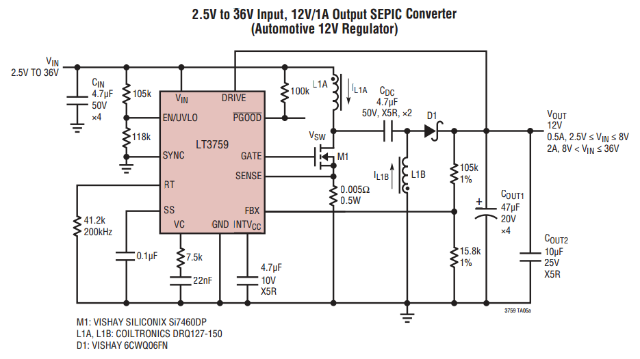
When VOUT is very low during startup or in the event of a short-circuit fault at the output, the switching regulator must operate at low duty cycles to keep the power switch current within the current limit range. This...

The relay power in the linear circuit is derived from a -120 V bias supply, while the transmit keying output from the Kenwood device is +12 V with a maximum current of 10 mA. A critical component of this...
This circuit is designed to indicate the power output level of any audio amplifier. It is simple, portable, and displays three power levels that can be set to any desired value. For a standard HiFi stereo power amplifier, such...
National Semiconductor has been designing and manufacturing integrated circuits (ICs) for switch-mode power supplies for many years. The application of these devices is typically straightforward, supported by comprehensive documentation. A common example of a switch-mode power supply is based...
A basic full wave rectified power supply is shown below. The transformer is chosen according to the desired load. For example, if the load requires 12V at 1amp current, then a 12V, 1 amp rated transformer would do. However,...