
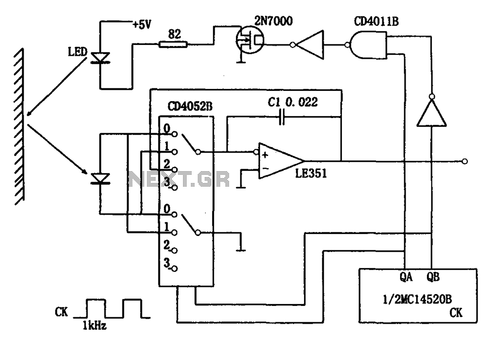
Reflected light intensity detecting circuit CD4052B CD4011B
The intensity of reflected light detection circuit is designed to provide a reliable means of measuring and analyzing light reflection from various surfaces. The core components, including infrared LEDs and photodiodes, work in conjunction to facilitate this measurement. The operation begins with the LED remaining off, which allows the photodiode to sense any ambient light or external interference. This initial detection phase captures the noise level, which is critical for establishing a baseline for further measurements.
Once the LED is turned on, the circuit transitions to detect the reflected light intensity. The photodiode's output during this phase is crucial as it directly correlates to the intensity of the reflected light. The integration circuit processes these signals, with the time intervals T1 and T2 carefully defined to ensure accurate readings. The hold time T3 is significant as it retains the last detected signal, allowing for analysis without immediate fluctuations from external interference.
The circuit's design allows it to function effectively even in environments with varying light conditions, thanks to the operational amplifiers that amplify the photodiode's output. The requirement for low input bias current ensures that the operational amplifiers do not introduce significant noise, thereby enhancing the accuracy of the reflected light measurement.
Furthermore, the circuit's versatility extends beyond simple light detection; it can also be utilized in applications such as distance measurement, tilt detection, and evaluating pass rates. The integration capacitor Ci plays a pivotal role in determining the circuit's gain, allowing for adjustments based on specific application needs. This adaptability makes the circuit suitable for various industrial and research applications, including those involving magnetic Hall elements, where precise measurements are essential. Overall, this circuit represents an efficient and effective solution for reflected light detection, with a robust design that minimizes interference and maximizes measurement accuracy. As shown for the intensity of reflected light detection circuit. The circuit consists of an infrared light-emitting diodes, photodiodes, CMOS analog switches, operational ampli fiers and other components. When the circuit to work, first the infrared light-emitting diode (LED) does not light, the photodiode received external interference signal converted to an electrical signal applied to the negative direction integration circuit, provided this period is T1; then make the LED light, the photodiode the received optical signal is converted to an electrical signal applied to the positive direction of the integrating circuit, this period is set T2. Let T1 T2. The circuit is displayed and held external interference signal, and are based reflected light intensity.
Hold signal this time is called hold time, referred to as T3. Integrator reset the corresponding time corresponding to T4. At the operating frequency (50Hz or 60Hz), the order to effectively avoid the interference of external synchronization, it is preferable that T1 T2 N/f (N an integer, f is the operating frequency), or take T1 T2 1/f. The circuit structure is simple, using the output power of 5 ~ 10mW infrared light-emitting diodes and photodiodes, can be detected at a distance of 10 ~ 100mm intensity of reflected light.
Circuit op amps input bias current should be much less than the photocurrent. Circuit gain depends on integration time and integration capacitor Ci. This can eliminate the interference detection circuit in addition to the intensity of the reflected light (reflected light ratio), it can also be used to detect the distance, tilt, and pass rates, especially for detection of various intensity. In addition, the circuit can be used for measuring magnetic Hall element and other measurements.
Related Circuits
Any PIC microcontroller equipped with an ADC and sufficient memory to accommodate the program can be utilized. An LED is pulsed after each ADC acquisition to indicate the processor's activity, allowing for verification of software functionality. The LCD voltmeter...
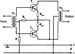
An amplifier is a device that accepts a varying input signal and produces an output signal that varies in the same way as the input but has a larger amplitude. The input signal may be a current, voltage, mechanical...
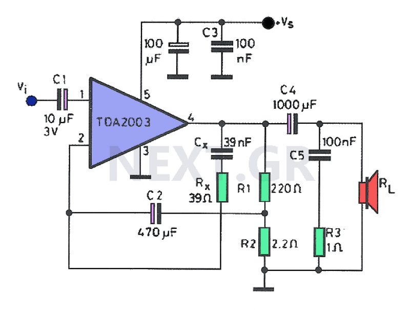
Often, a small amplifier is required to accommodate the needs of compact spaces. This amplifier can be configured as either mono or stereo, and its circuitry is capable of efficiently driving two small speakers. Constructing the amplifier necessitates only...
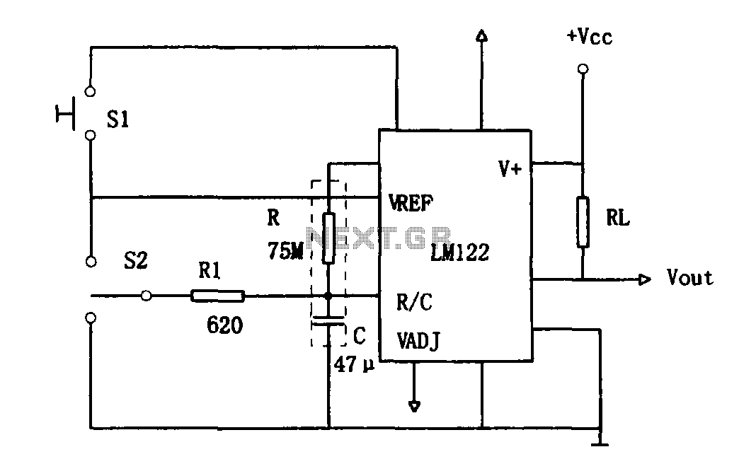
As illustrated in Figure 1, the circuit utilizes an LM122 timer. The circuit's start, reset, and stop functions are managed through switching operations. Switch S1 initiates the timing sequence when the timer is activated; thereafter, this switch has no...
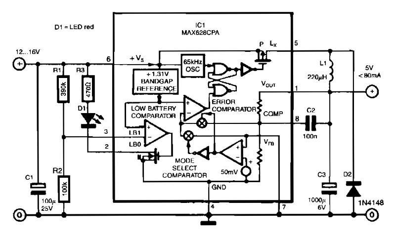
The circuit utilizes the MAX638CPA 5V CMOS Step Down Adjustable Switching Regulator IC, which converts an input voltage of 12 to 16 VDC into a stable 5VDC output. It requires only nine additional external components to complete the circuit....
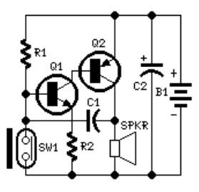
The system involves positioning a small magnet near the stalk switch SW1, which is connected to the hand or garments of the individual carrying the bag via a tiny cable. Due to the compact nature of the circuit, it...
Warning: include(partials/cookie-banner.php): Failed to open stream: Permission denied in /var/www/html/nextgr/view-circuit.php on line 713
Warning: include(): Failed opening 'partials/cookie-banner.php' for inclusion (include_path='.:/usr/share/php') in /var/www/html/nextgr/view-circuit.php on line 713