
1 hour LM122 timer circuit
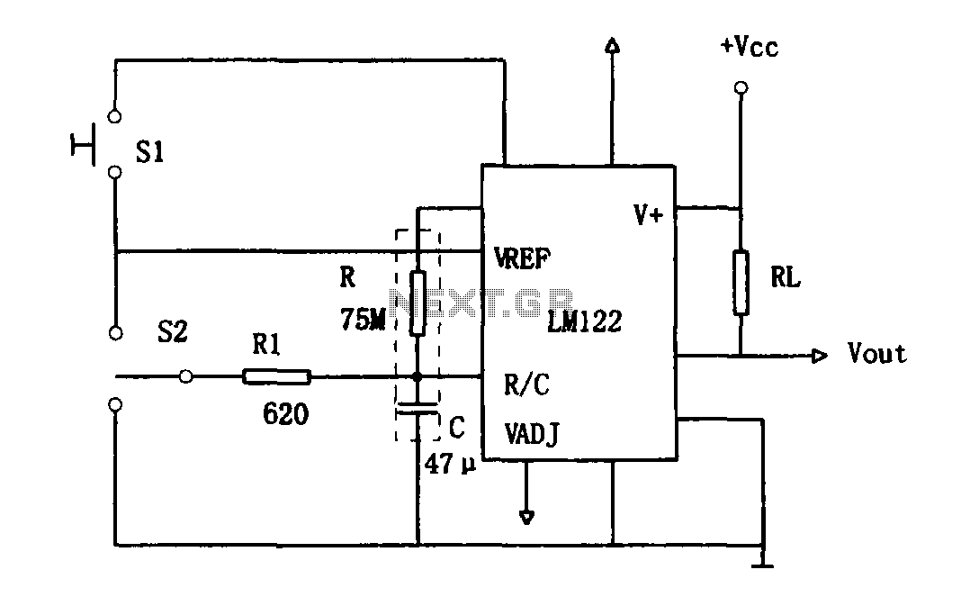
The LM122 timer circuit operates based on a combination of charging and discharging cycles controlled by the state of the switches. The circuit is designed to function in different modes, which are initiated by the action of S1 and S2. When switch S1 is pressed, the timer begins its timing cycle, allowing capacitor C to charge. The charging phase continues until the timer reaches the predetermined time or until S2 is activated to stop the timing process.
During the charging phase, the capacitor accumulates voltage, which is monitored at the R/C terminal. Once the voltage reaches a specific threshold, the timer transitions to the open state, allowing for the discharge of capacitor C. If the timing needs to be stopped before the set duration is completed, activating switch S2 interrupts the charging process, and the circuit enters a standby mode. In this mode, the voltage at the R/C terminal drops to zero, indicating that capacitor C is fully discharged and ready to receive a new start signal.
The reset function of the circuit is critical to its operation, as it allows the timer to maintain its output state regardless of the charging status of capacitor C. This ensures that when the timer is reset, it does not disrupt the ongoing processes and can resume operation smoothly when the start signal is received again. The design of this timer circuit provides flexibility in timing applications, making it suitable for various electronic projects where precise timing control is essential. The LM122 timer's integrated features, combined with the manual switching options, create a versatile and efficient timing solution.As shown in Figure 1 hour using a LM122 timer circuit. Start of the circuit, reset and stop halfway, etc. are converted by the switching operation. Figure, S1 to start timing when the timer is started, then this switch has no effect. S2 is centrally located in the "off" switch, the timer can switch through the conversion is completed: Charge - open - discharge. Since midway stop charging, even if not to the timer set time, the charging station will return to work status timer output lines.
When the C discharge, R / C terminal voltage is zero, the discharge position waiting for start signal S1. Even if the recovery position. Work status timer output line does not change, therefore, the timer is reset when the work which the state remains the same output line, in this moment, C starts charging again, start a timer to change working hours.
Related Circuits
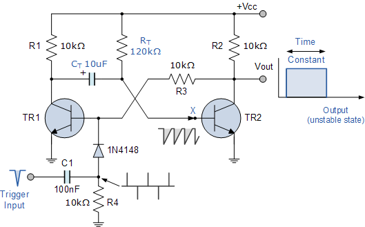
Electronics tutorial about the monostable multivibrator circuit, also known as a one-shot monostable multivibrator, used as a pulse generator circuit. The monostable multivibrator is a crucial component in electronic circuits, functioning as a pulse generator that produces a single output...
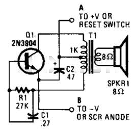
This is a simple low-level noise maker that is ideally suited for certain alarm applications. When the sounder is located in another part of the building, the sound level is loud enough to be heard but is not loud...
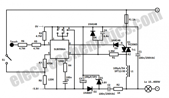
The SLB0586A integrated circuit from Siemens can be utilized to construct a straightforward touch light dimmer circuit, enabling the user to modify the intensity of a lamp. This circuit also incorporates a TIC206D component. The SLB0586A is a specialized touch-sensitive...
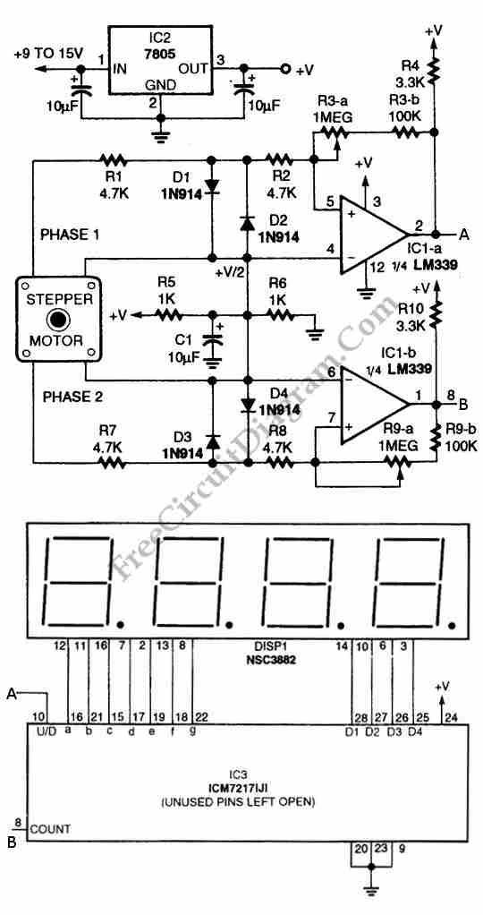
The circuit illustrated in the schematic diagram below allows for the visualization of the direction and shaft rotation of a stepper motor on an LED display. Instead of employing a digital rotation encoder as an input, this circuit utilizes...
This document outlines a simple PWM (Pulse Width Modulation) DC to AC voltage inverter circuit based on the SG3524 integrated circuit. The SG3524 is a fixed frequency PWM voltage regulator control circuit that offers indifferent outputs suitable for both...
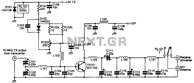
The SD1143 transistor offers a gain of approximately 14 dB in this circuit. Its design takes advantage of the fact that a 175-MHz device exhibits significantly higher gain when operated at lower frequencies. The amplifier was initially intended for...